Dilating expansion intramedullary nail

A technology of intramedullary nails and expansion grooves, applied in the field of intramedullary nails for fracture treatment, can solve problems such as unfavorable fracture healing, damage to bone marrow, and prolong operation time, so as to improve the effect of fracture healing, promote reconstruction and healing, and facilitate surgery Effect

Inactive Publication Date: 2008-10-29
肖亮星
View PDF5 Cites 6 Cited by
  • Summary
  • Abstract
  • Description
  • Claims
  • Application Information

AI Technical Summary

Problems solved by technology

However, it is found in practice that there are still the following defects: 1. Because the locking intramedullary nail is located at the two ends of the long bone, the surgical incision must be increased. The distance between the swing and the main positioning rod changes, so that the height gauge cannot be positioned accurately, resulting in the locking hole of the intramedullary nail and the positioning hole on the main positioning rod are no longer on the same plane, which often leads to drilling failure, requiring new CT or X-ray Down drilling not only prolongs the operation time, increases the difficulty of the operation, but also affects the effect of the operation; 3. The intramedullary nail and the corresponding locking nail have no pressure effect on the fracture line, and the fracture may still be loose or even staggered after fixation, so that the fracture The increased gap is not conducive to fracture healing; 4. After the intramedullary nail and corresponding locking are fixed, static fixation is formed, resulting in stress concentration on the intramedullary nail and corresponding locking, resulting in fracture with the internal fixation and / or corresponding locking; 5. Moreover, static fixation, due to the relationship between the elastic modulus, produces stress shielding on the fracture site, resulting in fracture nonunion; 6 From the perspective of fixation methods, the internal fixation and bone are mostly two-dimensional bodies, and the weak points in mechanics , it is difficult for this fixing system to achieve full-optimum shear bending resistance
7 The installation of the intramedullary nail needs to destroy the bone marrow and affect the blood supply of the bone
However, this technical solution obviously has the following deficiencies: 1. "There is always physiological stress stimulation in the whole fracture healing process", so it is not good for callus formation in the early stage of fracture, and may even cause bone resorption; Once the intramedullary nail is shortened under the action of external force, it is difficult to return, which weakens the stimulating effect of the physiological stress and significantly deteriorates the effect
However, this device has similar disadvantages to the above: there are also two ends at the control point of the large-headed conical nut and the central stud, and the twists and turns of the medullary cavity lead to difficulties in turning and advancing and retreating, which is not conducive to surgical implantation, and is also not conducive to taking out the locking nail after recovery , and even lead to the failure of the implantation operation or the large-headed conical nut completely detached from the control center stud and fell into the medullary cavity, increasing the difficulty of the removal operation and the pain of the patient
In fact, the disadvantages of this type of device are similar to the above, so I won’t repeat them here. At the same time, the medullary cavity may be distributed in a dumbbell shape due to the long limbs, the distal medullary cavity is too large (such as the lower part of the tibia) or the selected intramedullary nail is too long. If the distal end of the nail is stretched, the fixation effect may not be achieved, which affects the use of the device

Method used


Image

  • Dilating expansion intramedullary nail
  • Dilating expansion intramedullary nail
  • Dilating expansion intramedullary nail

Examples


Embodiment Construction

[0017] Now in conjunction with accompanying drawing and embodiment the present invention is described in further detail:

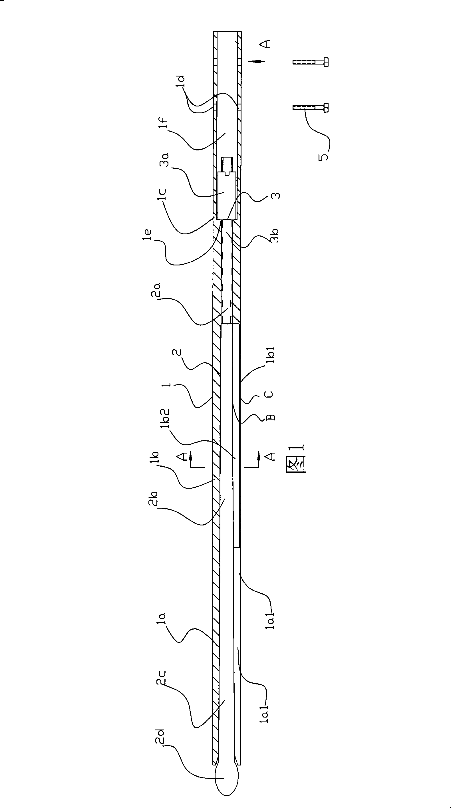
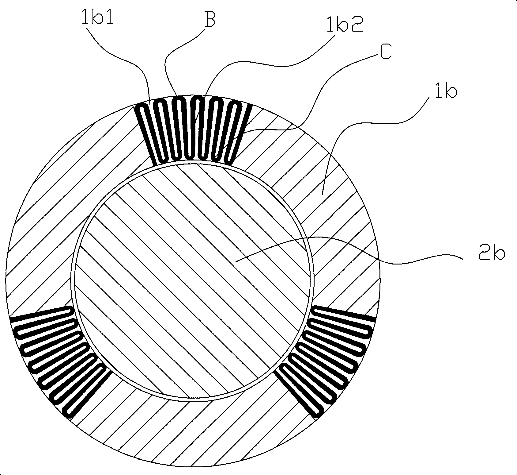
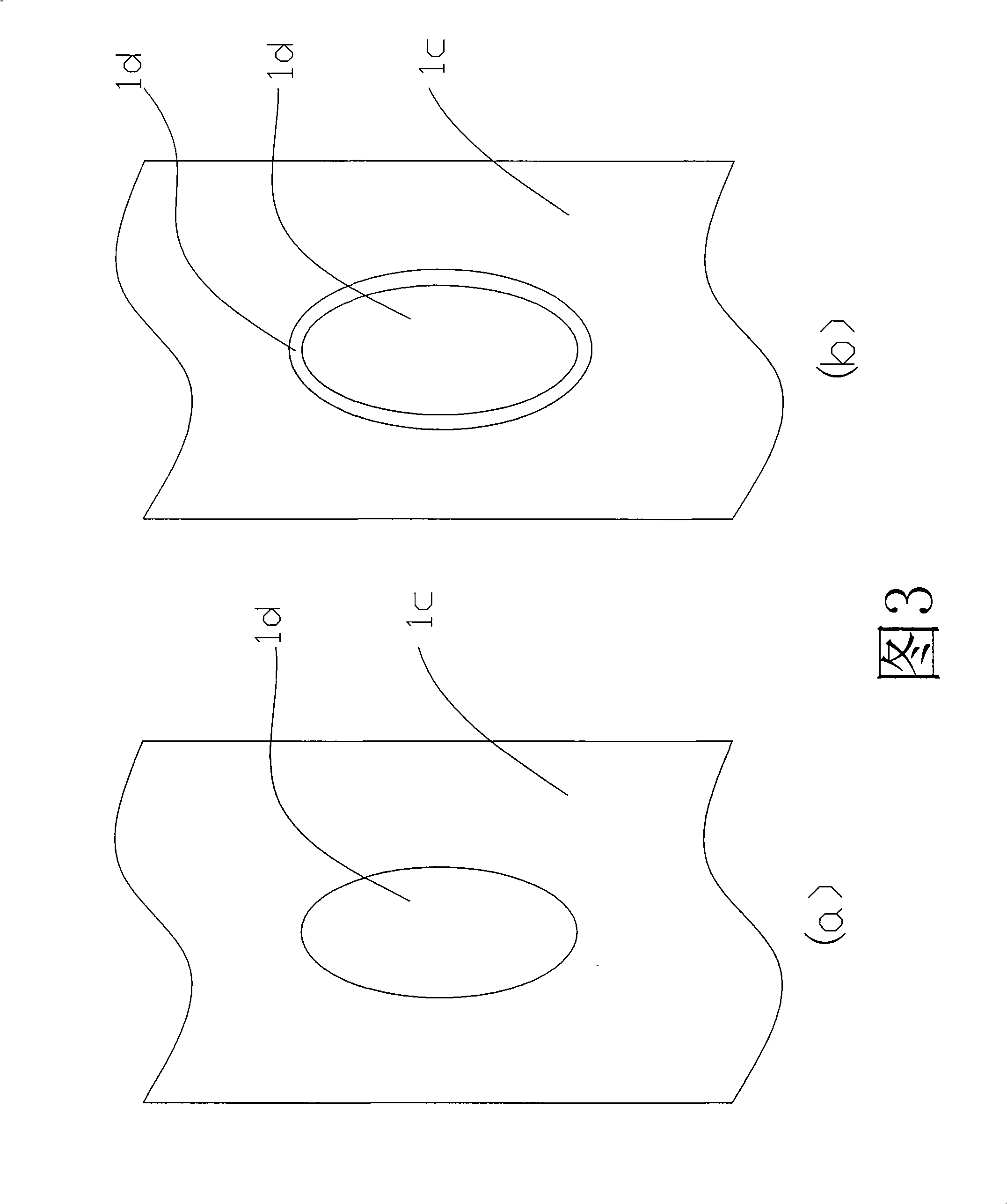
[0018] As shown in the figure, the present invention consists of a nail body 1 and a central rod 2. The nail body 1 is hollow tubular and includes three parts: a distal end 1a, a trunk 1b and a proximal end 1c. The trunk 1b of the nail body 1 and the tube of the distal end 1a There are three or more expansion grooves 1b1 and 1a1 in the longitudinal direction of the wall, and the main expansion grooves 1b1 are connected by alloy thin plates 1b2. The alloy thin plates 1b2 are corrugated. Distribution, the central rod 2 includes a proximal head 2a, a main body 2b and a distal head 2c, the inner hole of the trunk 1b and the distal end 1a of the nail body 1 is conical from thin to thick, and the corresponding main body 2b and distal head of the central rod 2 2c is conical from thin to thick, and the distal head 2c of the center rod 2 is provided with an expansi...


PUM


Abstract

An expandable intra-medullary nail comprises a nail body and a central rod arranged inside the nail body. The nail body is a hollow tube. The tube walls of the trunk and the far end of the nail body are provided with three or more than three expandable slots lengthways. The far end of the central rod is provided with an expandable head. The near end of the central rod is provided with a screw thread type axial tow attachment. The near end of the nail body is provided with a fixed structure which is a lock nail hole which is arranged at the near end of the nail body and is equipped with a lock nail. The present invention is characterized in that the lock nail is formed by a stainless steel nail body and degradable biological active material wrapped at the outside of the nail body, or the lock nail is made from the degradable biological active material, or the hole wall of the lock nail hole is provided with a layer of degradable biological active material. Compared with the prior art, as the stress simulation can be provided for the middle and later period of the fracture healing and the provided stress simulation is strengthened gradually, the nail of the present invention has the advantages of being good for the porosis at the early period of the fracture, being good for promoting the rebuilding and the cicatrization of bone during the medium and later periods of the fracture and improving the fracture cicatrization effect further.

Description

Technical field: [0001] The present invention relates to an orthopedic device, more specifically, the present invention relates to an intramedullary nail for treating fractures Background technique: [0002] Due to the development of modern traffic, there are more and more traffic accidents, and limb fractures are the most common in traffic accidents. There are various methods for the treatment of such fractures: splint or plaster fixation after manual reduction, bone traction, external fixation bracket fixation, surgical open reduction, plate fixation or intramedullary nail fixation. These methods have their own advantages and disadvantages, but the general direction of development is: small incision, less trauma, simple operation, short operation time, fast postoperative recovery, and early mobility and walking. [0003] Internal fixation always plays an important role in the treatment of fractures. In recent years, more advanced intramedullary nailing technology and equ...

Claims


Application Information

Patent Timeline
Patent Type & Authority Applications(China)
IPC IPC(8): A61B17/72A61B17/86
Inventor 肖亮星丘青中郭跃明江泽平梁少娴李挺威
Owner 肖亮星
Why Eureka
Try Eureka