Pressure casting non-sand concrete pile

A technology of sand-free concrete and grouting, which is applied to sheet pile walls, buildings, and foundation structure engineering, and can solve problems such as difficulty in meeting the bearing capacity and anti-seepage level requirements of river embankments at the same time

Inactive Publication Date: 2008-10-29
UNIV OF SCI & TECH BEIJING
View PDF0 Cites 13 Cited by
  • Summary
  • Abstract
  • Description
  • Claims
  • Application Information

AI Technical Summary

Problems solved by technology

[0003] It is to solve the problem that the ordinary pile-soil composite foundation is difficult to meet the requirements of the bearing capacity and anti-seepage level of river embankments at the same

Method used


Image

  • Pressure casting non-sand concrete pile
  • Pressure casting non-sand concrete pile
  • Pressure casting non-sand concrete pile

Examples


Embodiment 1

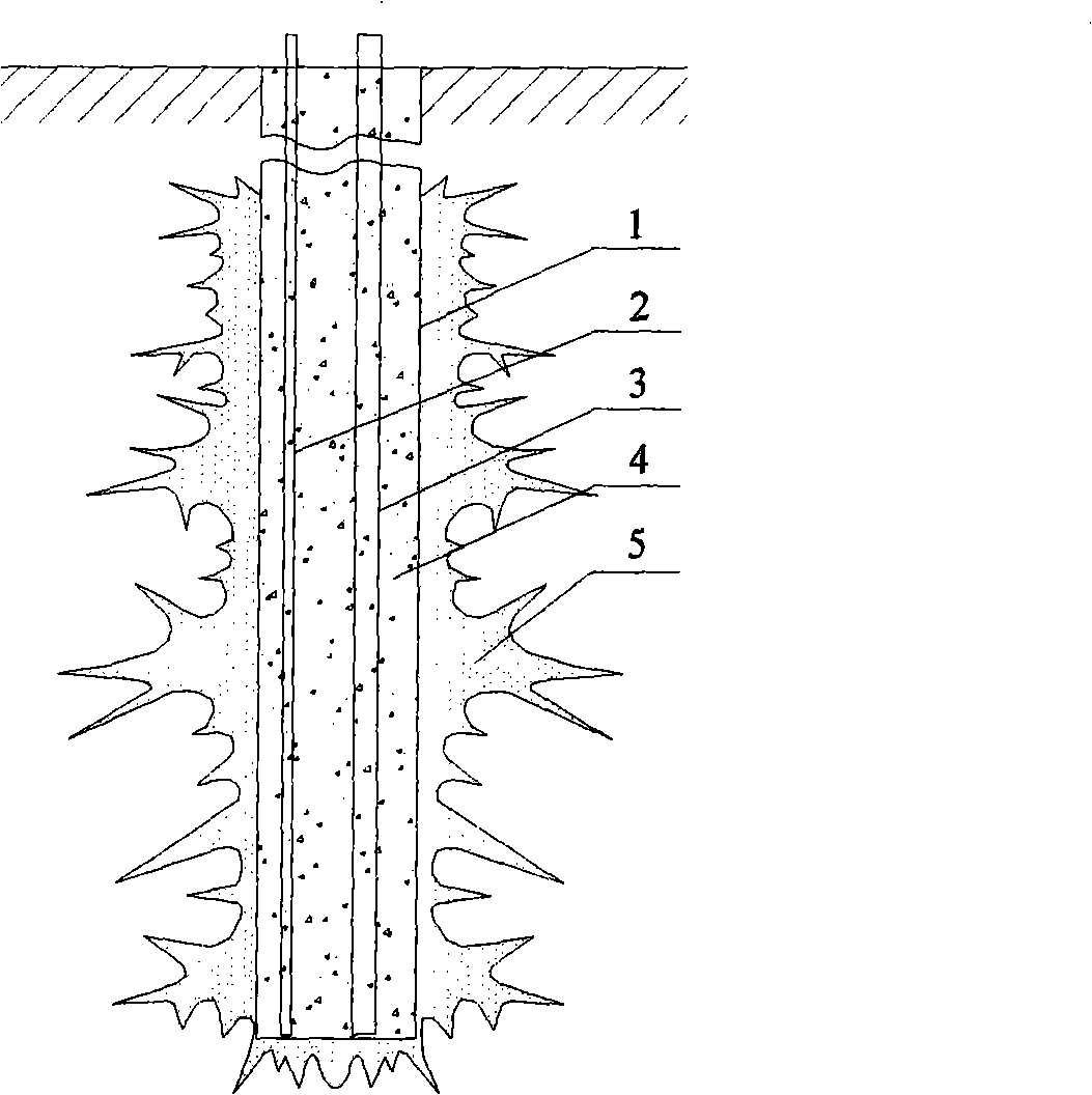
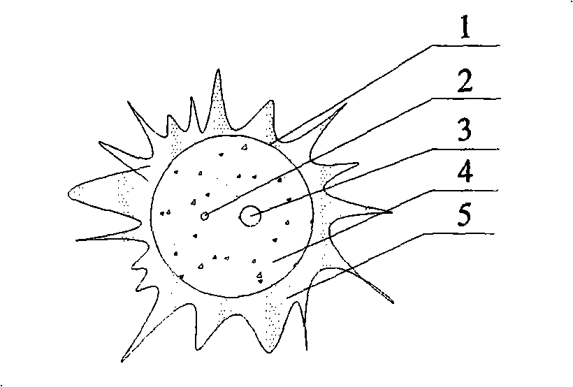
[0015] The pressure grouting sandless concrete pile shown in the figure, 1 is the borehole, 2 is the grouting pipe, 3 is the sleeve valve pipe, 4 is graded gravel or crushed stone, 5 is the grouting body, 6 is the sleeve valve pipe The grout stop piston, 7 is the grouting hole of the sleeve valve pipe, the 8 is the flower pipe of the sleeve valve pipe, and the 9 is a rubber sleeve. In the implementation process, first use the hole-forming machine to form the borehole 1 to the design depth of the pile body, insert the grouting pipe 2 and the sleeve valve pipe 3, the length of the grouting pipe 2 and the sleeve valve pipe 3 is the same as the depth of the borehole 1, and then fill in the gradation For gravel or crushed stone 4, use the grouting pipe 2 to carry out the first grouting. The grout is related to the undisturbed soil conditions, pile hole depth, position and grouting sequence. According to the site conditions of the Yellow River embankment in this embodiment, the desi...

Embodiment 2

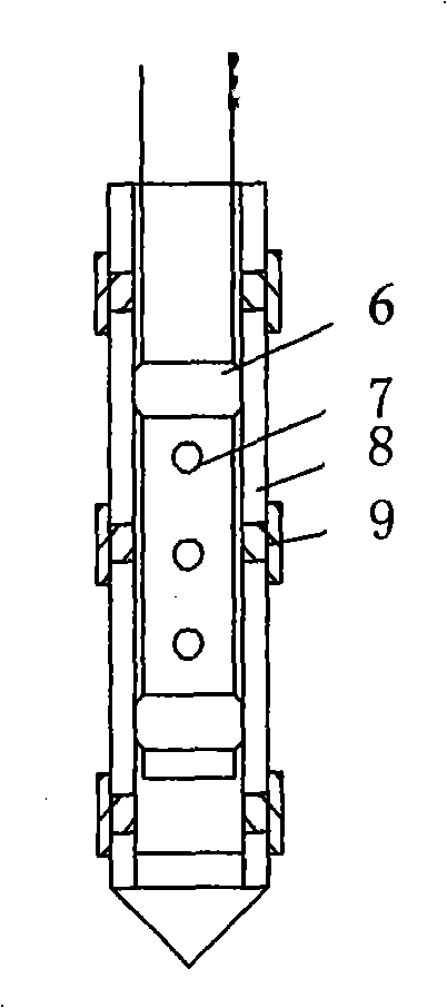
[0017] In the implementation process, first use the hole-forming machine to form the borehole 1 to the design depth of the pile body, insert the grouting pipe 2 and the sleeve valve pipe 3, the length of the grouting pipe 2 and the sleeve valve pipe 3 is the same as the depth of the borehole 1, and then fill in the gradation For gravel or crushed stone 4, use the grouting pipe 2 to carry out the first grouting. The grout is related to the undisturbed soil conditions, pile hole depth, position, and grouting sequence. According to the site conditions of this example, the designed secondary medium and high pressure grouting pressure is 1-3 MPa. During the secondary grouting process, it is set as a sleeve valve pipe The grout stopper 6 is at different positions, and the grout is released from the grouting hole 7 of the sleeve valve pipe. Due to the pressure of the grout, the rubber sleeve 9 is pushed away, and finally a secondary high-pressure grouting is performed on various parts...


PUM


Abstract

A pressure grouting non-fines concrete pile belongs to the construction engineering field, and is particularly applicable to strengthening river levees and reinforcing road-widening lap joints. The pressure grouting non-fines concrete pile comprises a borehole (1), a grouting pipe (2), a sleeve valve pipe (3), graded gravels or crushed stones (4) and a grouting body (5), wherein, the sleeve valve pipe (3) is composed of a sleeve valve pipe grout stop piston (6), a sleeve valve pipe grout injecting hole (7), a sleeve valve pipe screen tube (8) and a rubber bush (9). During the implementation process, a boring machine is firstly utilized to form the borehole (1) until the design depth of the non-fines concrete pile is reached, the grouting pipe (2) and the sleeve valve pipe (3) with the length of the both equal to the depth of the borehole (1) are inserted, then the graded gravels or the crushed stones (4) are filled in, and finally the grouting pipe (2) is utilized to carry out first grouting, the amount of which is equal to the grout output of the borehole (1); after the grout is initially condensed, the sleeve valve pipe (3) is utilized for carrying out secondary middle-high pressure grouting, the pressure of which is 1 to 5 MPa, and the grouting flow rate is 10 to 60 L/min. The pressure grouting non-fines concrete pile has the advantages that the design is reasonable, the construction is simple, the bearing capacity is high, and the anti-seepage capacity of the reinforced section is improved.

Description

Technical field: [0001] The invention belongs to the field of construction engineering, and in particular relates to a pressure grouting sandless concrete pile suitable for reinforcement of river embankments and road widening and lap joint reinforcement. Background technique: [0002] my country has a vast territory and complex geological conditions. There are soft rocks, soft soils and soft soils of various origins, especially in the relatively developed regions in the east and southeast. The main characteristics of this type of rock and soil include: compression resistance (or shear) low strength, high porosity, large compressibility, etc. Aiming at this kind of geotechnical problems, pile-soil composite foundation has been widely used due to its advantages of simple process, convenient construction and low cost. However, for river embankments or original subgrades with relatively dense soil, ordinary compacted gravel piles and powder-sprayed piles are difficult to constru...

Claims


Application Information

Patent Timeline
IPC IPC(8): E02D5/36E02D5/62
Inventor 高永涛吴顺川孙金海
Owner UNIV OF SCI & TECH BEIJING
Why Eureka
Try Eureka