Plasma processing apparatus

A technology for processing equipment and plasma, which is applied in the field of microelectronics, can solve problems such as damage, low reliability, and difficulty in guaranteeing coating quality, and achieve the effects of reducing use costs, avoiding frequent disassembly and assembly, and reliable protection effects

Active Publication Date: 2008-10-29
BEIJING NAURA MICROELECTRONICS EQUIP CO LTD
View PDF0 Cites 11 Cited by
  • Summary
  • Abstract
  • Description
  • Claims
  • Application Information

AI Technical Summary

Problems solved by technology

For the showerhead electrode 163, the plasma in the reaction chamber 12 will bombard its lower surface during the working process of the plasma processing equipment 1, and the gas will also chemically react with the showerhead electrode 163, causing it to be damaged; when the damage reaches To a certain extent, the showerhead electrode 163 can no longer be used and must be replaced, which makes the showerhead electrode 163 one of the main consumables of the plasma processing equipment 1
Due to the high cost and relatively large consumption, the frequent replacement of the shower head electrode 163 significantly increases the use cost of the plasma processing device 1
[0010] A layer of plasma-resistant coating can be sprayed on the surface of the shower head electrode 163 facing the reaction chamber 12, so as to reduce the consumption of the shower head electrode 163 to a certain extent, but this method has a big disadvantage
Due to the small size and complex structure of the vent hole in the showerhead electrode 163, the spraying process required to form a reliable coating on its surface has high technical difficulty, and the quality of the coating is difficult to guarantee, which leads to the corrosion of the showerhead electrode 163. The situation is still serious
The reliability of the above-mentioned coatings can be improved by adopting a more advanced spraying process, but the cost of the spraying process itself will increase significantly, and the overall cost of the equipment will remain at a relatively high level without effectively reducing
It can be seen that the above-mentioned method of prolonging the life of the nozzle electrode 163 has high cost, high technical difficulty and low reliability

Method used


Image

  • Plasma processing apparatus
  • Plasma processing apparatus
  • Plasma processing apparatus

Examples


Embodiment Construction

[0029] The core of the present invention is to provide a plasma processing device, which can simply and reliably prolong the life of the nozzle electrode, and further effectively reduce the use cost of the plasma processing device.

[0030] In order to enable those skilled in the art to better understand the solution of the present invention, the present invention will be further described in detail below in conjunction with the accompanying drawings and specific embodiments.

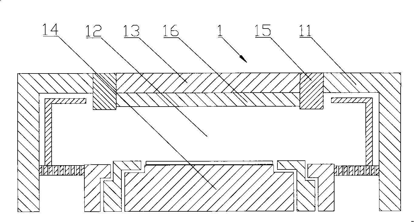
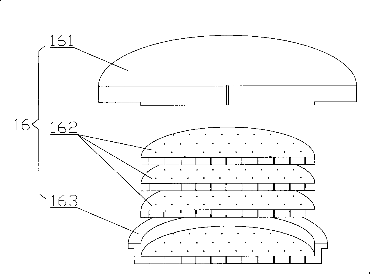
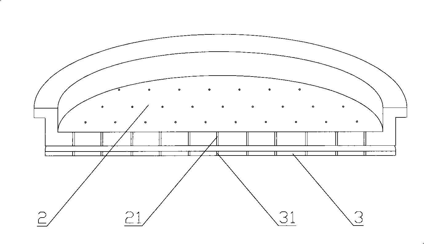
[0031] Please refer to image 3 and Figure 4 , image 3 It is a schematic diagram of the setting position of the liner provided by the present invention; Figure 4 It is a structural schematic diagram of a specific embodiment of the liner provided by the present invention.

[0032] In a specific embodiment, the plasma processing equipment provided by the present invention also includes a casing, in which there is a reaction chamber, and the top and bottom of the reaction chamber are respectively pro...


PUM


Abstract

The invention discloses a plasma treatment device that comprises a burner cap electrode, and gas flows through an air inlet running through the burner cap electrode to enter a reaction chamber of the plasma treatment device; a scaleboard that can be assembled and disassembled is arranged on the burner cap electrode facing to the surface; the scaleboard is generally parallel to the burner cap electrode and provided with a through hole corresponding to the air inlet so as to facilitate the gas to enter the reaction chamber through the through hole. The technical difficulty and the cost required by the scaleboard are comparatively low, but the insulation effect of the scaleboard is reliable and stable; the scaleboard can be conveniently replaced when being corroded to a predetermined degree, therefore, the service life of the burner cap electrode can be obviously prolonged and the cost is saved.

Description

technical field [0001] The invention relates to the technical field of microelectronics, in particular to a plasma processing device. Background technique [0002] Plasma processing equipment has been widely used in the field of microelectronics technology. [0003] Please refer to figure 1 , figure 1 It is a schematic structural diagram of a typical plasma processing equipment in the prior art. [0004] Plasma processing equipment 1 generally includes a housing 11, in which there is a reaction chamber 12, and the top and bottom of the reaction chamber 12 are respectively provided with an upper plate 13 and a lower plate 14 correspondingly. The upper plate 13 is isolated from the casing 11 by an insulating member 15; the top of the lower plate 14 can support the workpiece to be processed. The above-mentioned processed parts shall include wafers and other processed parts having the same processing principle. The meaning of the workpiece described below is the same. [0...

Claims


Application Information

Patent Timeline
Patent Type & Authority Applications(China)
IPC IPC(8): H05H1/46H01L21/00H01J37/32
Inventor 姚立强
Owner BEIJING NAURA MICROELECTRONICS EQUIP CO LTD
Why Eureka
Try Eureka