Bearing device for wheel
A bearing device and wheel technology, applied in the direction of rotating bearings, bearings, axles, etc., can solve the problems that the optimal stiffness cannot always be obtained, and achieve the effects of increasing stiffness, suppressing damage to balls, and improving noise characteristics
- Summary
- Abstract
- Description
- Claims
- Application Information
AI Technical Summary
Problems solved by technology
Method used
Image
Examples
no. 1 approach
[0040] Preferred embodiments of the present invention will be described below with reference to the accompanying drawings.
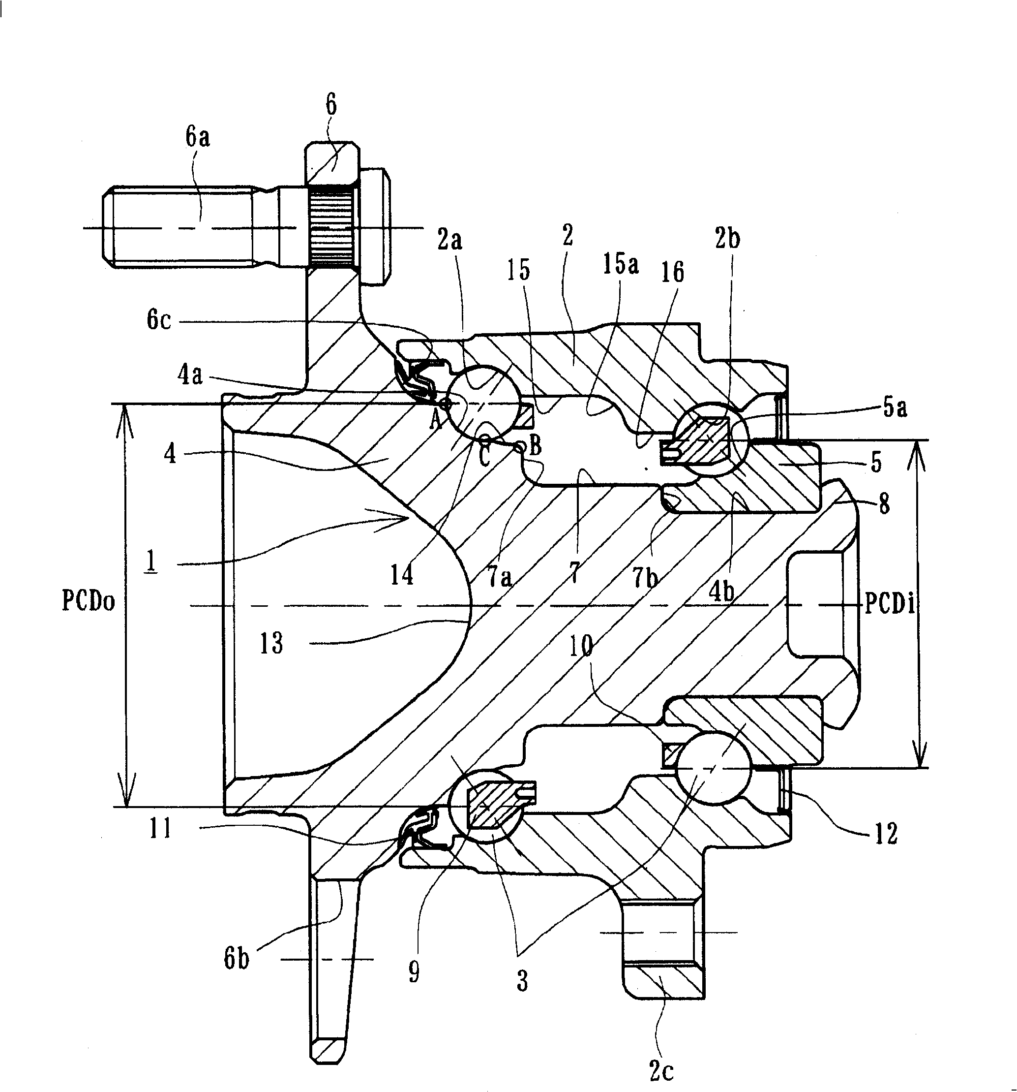
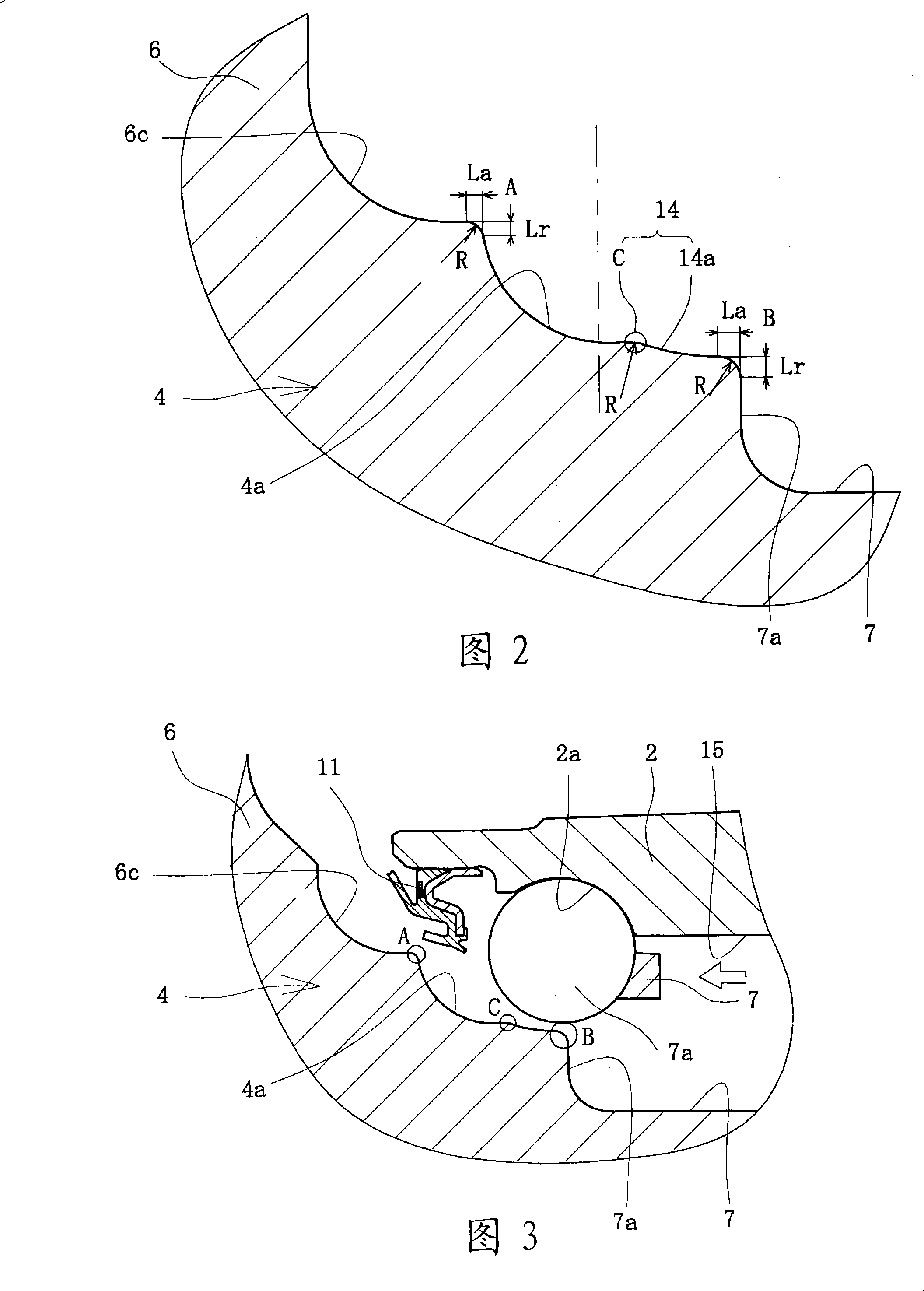
[0041] figure 1 It is a longitudinal sectional view showing the first embodiment of the bearing device for a wheel of the present invention, and FIG. 2 is figure 1 Figure 3 is an enlarged sectional view of the situation during the assembly of the inner ball set onto the inner raceway surface of the hub wheel. In the following description, the term "outside" of the device (left-hand side in the figure) refers to the side that is located outside the vehicle body when the bearing device is installed on the vehicle body, and the term "inside" (right-hand side in the figure) of the device Side) refers to the side that is located inside the vehicle body when the bearing unit is installed on the vehicle body.
[0042] figure 1 The bearing arrangement for a wheel of the invention shown is of the third generation type for a driven wheel, comprising an inner...
no. 2 approach
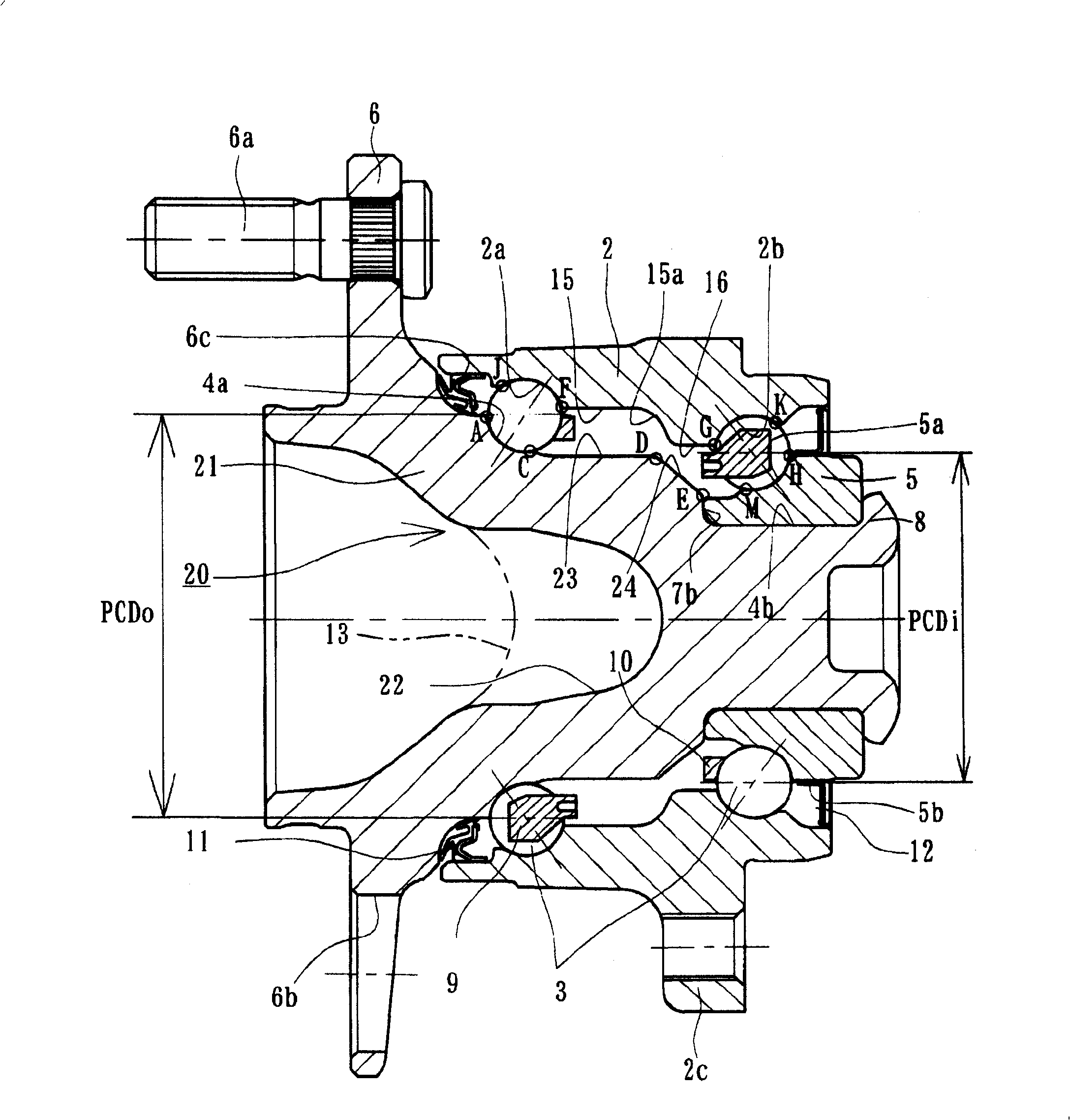
[0059] Figure 4 is a longitudinal sectional view showing a second embodiment of the bearing device for a wheel of the present invention, Figure 5 Yes Figure 4 An enlarged cross-sectional view of the hub wheel, Image 6 is an enlarged cross-sectional view of the situation during the assembly of the inner ball set on the inner raceway surface of the hub wheel, and Fig. 7 is Figure 4 An enlarged sectional view of the outboard bearing row, Figure 8 is Figure 4 An enlarged cross-sectional view of the inboard bearing row of Figure 9 It is an explanatory diagram showing the grinding work performed on the outer parts after heat treatment, Figure 10 (a) is an explanatory diagram showing the grinding operation performed after the heat treatment of the wheel hub, Figure 10 (b) is an explanatory view showing the grinding operation performed on the inner ring after the heat treatment. Since the second embodiment differs from the first embodiment only in the structure of the w...
no. 3 approach
[0070] Figure 11 It is a longitudinal sectional view showing a third embodiment of the bearing device for a wheel of the present invention. The same reference numerals are used here to designate the same components with the same functions as those used in the previous embodiments.
[0071] The bearing arrangement is of the second generation type for driven wheels, comprising an inner part 28 , an outer part 29 and a double row of balls 3 , 3 housed between the inner part 28 and the outer part 29 in a free rolling manner. The inner member 28 includes a pair of inner rings 30, 5 formed with inner raceway surfaces 30a, 5a on their outer peripheral surfaces.
[0072] The outer member 29 is made of medium carbon steel (such as S53C) with a carbon content of 0.40 to 0.80% by weight, and is integrally formed with a wheel mounting flange 6 on its outer peripheral surface, and integrally formed with a double flange on its inner peripheral surface. Outer raceway surfaces 2a, 2b. The...
PUM
 Abstract
Description
Claims
Application Information
 - R&D
- Intellectual Property
- Life Sciences
- Materials
- Tech Scout
- Unparalleled Data Quality
- Higher Quality Content
- 60% Fewer Hallucinations
Browse by: Latest US Patents, China's latest patents, Technical Efficacy Thesaurus, Application Domain, Technology Topic, Popular Technical Reports.
© 2025 PatSnap. All rights reserved.Legal|Privacy policy|Modern Slavery Act Transparency Statement|Sitemap|About US| Contact US: help@patsnap.com


