Transmitter and method for controlling same

a technology for transmitting devices and transmitters, applied in the field of transmitters, can solve the problems that the power amplifier disposed at the final stage of the transmission unit of the communication device occupies 50% or more of the power consumption of the entire transmitter, and achieves excellent power efficiency and favorable noise characteristics

Active Publication Date: 2013-06-06
NEC CORP
View PDF12 Cites 15 Cited by
  • Summary
  • Abstract
  • Description
  • Claims
  • Application Information

AI Technical Summary

Benefits of technology

[0020]According to the present invention, it is possible to provide a transmitter having favorable noise characteristics and excellent power efficiency, and a method for controlling the same.

Problems solved by technology

In particular, a power amplifier disposed at a final stage of a transmission unit of a communication device occupies 50% or more of the power consumption of the entire transmitter.

Method used


Image

  • Transmitter and method for controlling same
  • Transmitter and method for controlling same
  • Transmitter and method for controlling same

Examples


first exemplary embodiment

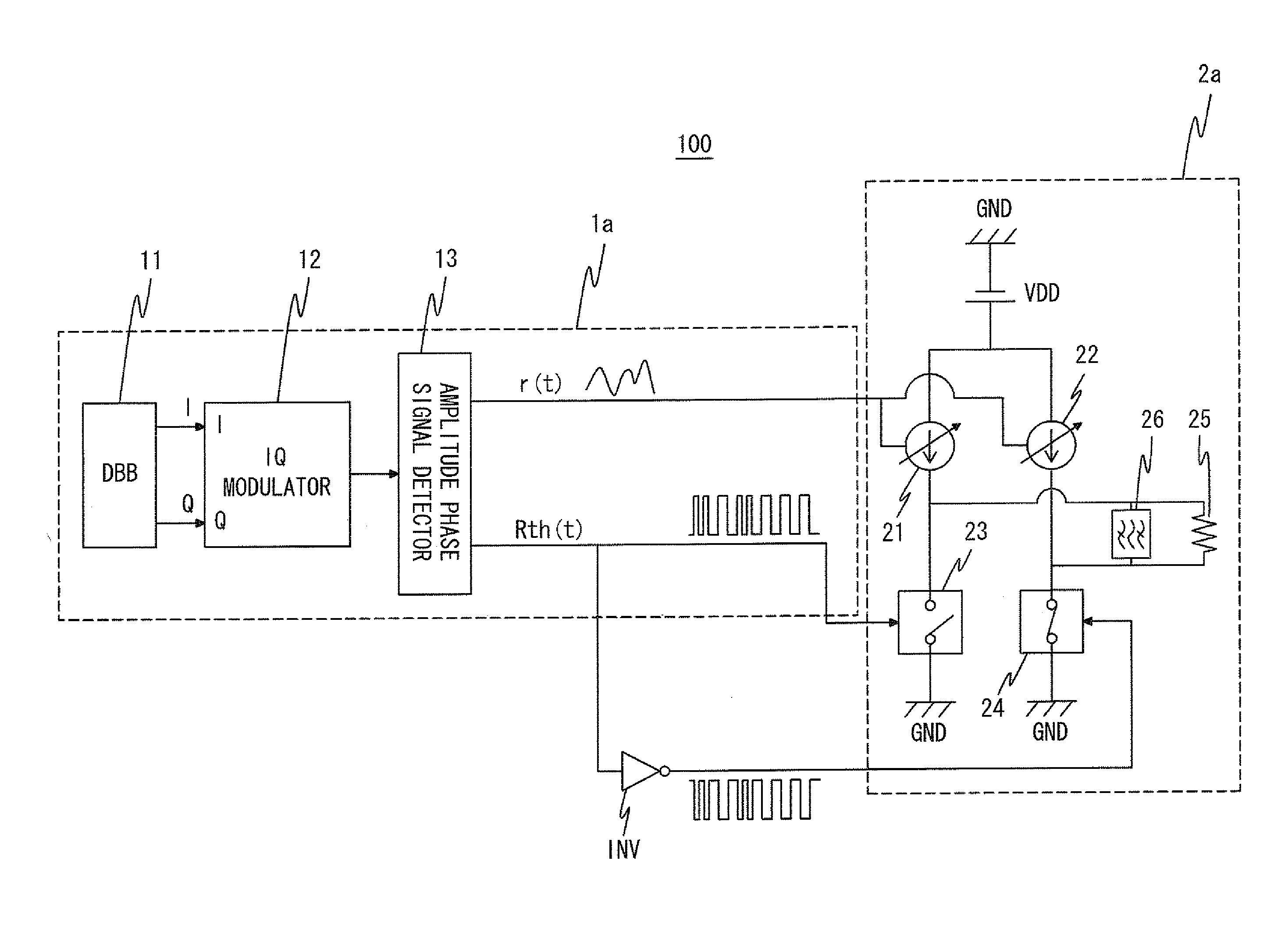
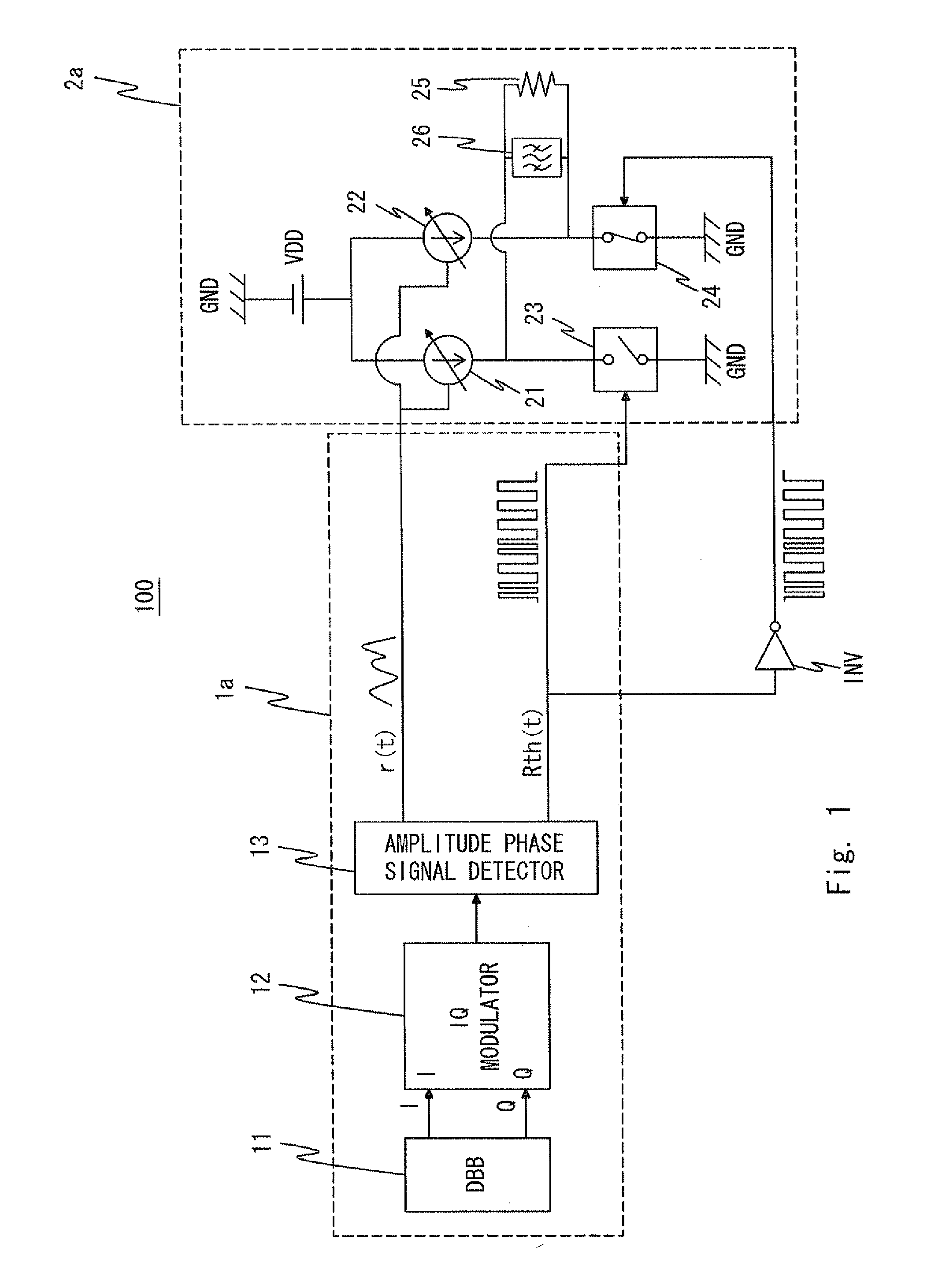
[0044]First, a transmitter according to a first exemplary embodiment of the present invention will be described. FIG. 1 is a block diagram showing a configuration of a transmitter 100 according to the first exemplary embodiment. The transmitter 100 includes an RF signal generator 1a and a current mode class-D amplifier 2a.

[0045]The RF signal generator 1a includes a digital baseband (hereinafter referred to as “DBB”) 11, an IQ modulator 12, and an amplitude phase signal detector 13. The DBB 11 generates IQ signals.

[0046]The IQ modulator 12 converts the IQ signals into an RF signal RF(t) by IQ modulation. Here, “t” is a variable representing time. The RF signal RF(t) is generally expressed by the following expression (2) using an amplitude signal r(t) and a phase signal th(t).

RF(t)=r(t)·th(t)  (2)

[0047]The phase signal th(t) is expressed by the following expression (3).

th(t)=cos(ωc·t+theta(t))  (3)

where ωc is an angular velocity obtained by multiplying a carrier frequency by 2π, and ...

second exemplary embodiment

[0084]Next, a transmitter according to a second exemplary embodiment of the present invention will be described. FIG. 15 is a block diagram showing a configuration of a transmitter 200 according to the second exemplary embodiment. The transmitter 200 has a configuration in which the RF signal generator 1a of the transmitter 100 is replaced with an RF signal generator 1b. The other components of the transmitter 200 are similar to those of the transmitter 100, so the description thereof is omitted.

[0085]The RF signal generator 1b has a configuration in which a divider 14 is added to the RF signal generator 1a of the transmitter 100 and the amplitude detector 131 is replaced with an amplitude detector 133. In the transmitter 200, the DBB 11 outputs IQ signals to each of the divider 14 and the amplitude detector 133.

[0086]The divider 14 outputs signals obtained by dividing the IQ signals by the amplitude signal output from the amplitude detector 133. Radio signals Ib(t) and Qb(t) which ...


PUM


Abstract

An RF signal generator divides an input radio signal into an amplitude signal and a phase signal and outputs the amplitude signal and the phase signal. A switching amplifier amplifies the radio signal with the amplitude signal and the phase signal. The switching amplifier includes at least one variable current sources that is controlled by the amplitude signal and supplies a current to the switching amplifier. The switching amplifier includes at least one switching elements that connects the variable current sources to one of a terminal connected a ground potential and an output terminal of the switching amplifier according to the phase signal.

Description

TECHNICAL FIELD[0001]The present invention relates to a transmitter used for a communication device, such as a cellular phone or a wireless LAN, and a method for controlling the same, and more particularly, to a transmitter having an excellent power efficiency, and a method for controlling the same.BACKGROUND ART[0002]A transmission unit of a communication device, such as a cellular phone or a wireless LAN, is required to operate with low power consumption. Such a transmission unit of a communication device is required to operate with low power consumption regardless of the magnitude of output power, and is also required to ensure a high accuracy of transmission signals. In particular, a power amplifier disposed at a final stage of a transmission unit of a communication device occupies 50% or more of the power consumption of the entire transmitter. For this reason, the power amplifier disposed at the final stage of the transmission unit of the communication device needs to have a hi...

Claims


Application Information

Patent Timeline
Patent Type & Authority Applications(United States)
IPC IPC(8): H04W52/02
CPCH03F1/0222H03F3/189H03F3/217H03F3/24H03F2200/408H03F2200/91H04W52/0209H03F3/245H03F2200/336
Inventor HORI, SHINICHI
Owner NEC CORP
Why Eureka
Try Eureka