Magnetoresistive effect transducer having longitudinal bias layer directly connected to free layer

a transducer and longitudinal bias technology, applied in the field of magnetoresistive (mr) effect transducers, can solve the problems of increasing the noise in reproduced signals, difficult to apply a sufficiently large magnetic bias field to the free ferromagnetic layer, and reducing so as to improve the noise characteristics improve the manufacturing yield of mr effect transducers, and improve the effect of noise characteristics

Inactive Publication Date: 2005-10-06
NEC CORP
View PDF20 Cites 15 Cited by
  • Summary
  • Abstract
  • Description
  • Claims
  • Application Information

AI Technical Summary

Benefits of technology

[0011] It is an object of the present invention to improve the noise characteristics of MR effect transducers.
[0012] Another object of the present invention is to improve the manufacturing yield of MR effect transducers.
[0013] According to the present invention, in a magnetoresistive effect transducer including a pinning layer, a pinned layer, a free layer and a non-magnetic layer inserted between the pinned layer and the free layer, a longitudinal bias layer is connected directly to a part of the free layer to apply a bias magnetic field to the free layer, thus biasing a magnetization direction of the free layer so that the magnetization direction of the free layer coincides with that of the longitudinal bias layer. Thus, the noise characteristics are improved.
[0014] Also, an uppermost layer of the MTJ or spin value is patterned by a milling process, so that the uppermost layer has a smaller pattern than the other layers. This would prevent metal particles or contamination from adhering to the barrier layer, thus improving the manufacturing yield.

Problems solved by technology

In the above-described prior art MR effect transducers, however, since the free ferromagnetic layer is separated from the longitudinal bias ferromagnetic layer by a magnetic isolation layer, it is difficult to apply a sufficiently large magnetic bias field to the free ferromagnetic layer, which would increase the noise in reproduced signals.
This would decrease the manufacturing yield of MR effect transducers.

Method used


Image

  • Magnetoresistive effect transducer having longitudinal bias layer directly connected to free layer
  • Magnetoresistive effect transducer having longitudinal bias layer directly connected to free layer
  • Magnetoresistive effect transducer having longitudinal bias layer directly connected to free layer

Examples


first embodiment

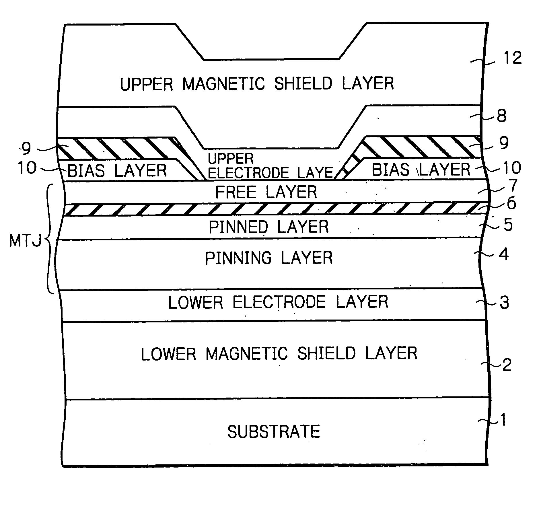
[0057] In FIG. 5, which illustrates the MTJ-type MR effect transducer according to the present invention, a lower magnetic shield layer 2, a lower electrode layer 3, a pinning layer 4, a pinned layer 5, a barrier layer 6 and a free layer 7 are sequentially formed on a substrate 1.

[0058] Also, patterned longitudinal bias layers 10 and patterned insulating layers 9 are formed on the free layer 7.

[0059] Further, an upper electrode layer 8 and an upper magnetic shield layer 12 are sequentially formed on the free layer 7 and the insulating layers 9, thus completing the MTJ-type MR effect transducer of FIG. 5.

[0060] In the MTJ-type MR effect transducer of FIG. 5, a tunnel current flows from the lower electrode 3 via the pinning layer 4, the pinned layer 5, the barrier layer 6 and the free layer 7 to the upper electrode layer 8. In this case, since the longitudinal bias layers 10 deviate from the path of the tunnel current, the tunnel current never flows from or to the longitudinal bias ...

second embodiment

[0064] In FIG. 6, which illustrates the MTJ-type MR effect transducer according to the present invention, a lower magnetic shield layer 2, a lower electrode layer 3, a pinning layer 4, a pinned layer 5, a barrier layer 6 and a free layer 7 are sequentially formed on a substrate 1.

[0065] Also, a patterned upper electrode layer 8 is formed on the free layer 7.

[0066] Further, a patterned longitudinal bias layer 10 and an upper magnetic shield layer 12 are sequentially formed on the free layer 7 and the upper electrode layer 8, thus completing the MTJ-type MR effect transducer of FIG. 6.

[0067] In the MTJ-type MR effect transducer of FIG. 6, a tunnel current flows from the lower electrode 3 via the pinning layer 4, the pinned layer 5, the barrier layer 6 and the free layer 7 to the upper electrode layer 8. In this case, since the longitudinal bias layer 10 deviates from the path of the tunnel current, the tunnel current never flows from or to the longitudinal bias layer 10.

[0068] In t...

third embodiment

[0071] In FIG. 7, which illustrates the MTJ-type MR effect transducer according to the present invention, a lower magnetic shield layer 2, a lower electrode layer 3, a pinning layer 4, a pinned layer 5 and a barrier layer 6 are sequentially formed on a substrate 1.

[0072] Also, a patterned free layer 7 patterned insulating layers 9 and patterned longitudinal bias layers 10 are formed on the barrier layer 6.

[0073] Further, an upper electrode layer 8 and an upper magnetic shield layer 12 are sequentially formed on the free layer 7 and the bias layers 10, thus completing the MTJ-type MR effect transducer of FIG. 7.

[0074] In the MTJ-type MR effect transducer of FIG. 7, a tunnel current flows from the lower electrode 3 via the pinning layer 4, the pinned layer 5, the barrier layer 6 and the free layer 7 to the upper electrode layer 8. In this case, since the longitudinal bias layers 10 deviate from the path of the tunnel current, the tunnel current never flows from or to the longitudina...


PUM

PropertyMeasurementUnit
thickaaaaaaaaaa
thickaaaaaaaaaa
thickaaaaaaaaaa

Abstract

In a magnetoresistive effect transducer including a pinning layer, a pinned layer, a free layer and a non-magnetic layer inserted between the pinned layer and the free layer, a longitudinal bias layer is connected directly to a part of the free layer to apply a bias magnetic field to the free layer, thus biasing a magnetization direction of the free layer so that the magnetization direction of the free layer coincides with that of the longitudinal bias layer.

Description

BACKGROUND OF THE INVENTION [0001] 1. Field of the Invention [0002] The present invention relates to a magnetoresistive (MR) effect transducer which can be used as a read head for sensing a leakage magnetic field from a magnetic medium. [0003] 2. Description of the Related Art [0004] MR effect transducers are divided into a ferromagnetic tunneling junction (MTJ)-type and a spin value type. [0005] An MTJ structure of the MTJ-type MR effect transducer is constructed by a pinned ferromagnetic layer, a free ferromagnetic layer and an insulating barrier layer sandwiched by the pinned ferromagnetic layer and the free ferromagnetic layer. [0006] On the other hand, a spin value structure of the MTJ-type MR effect transducer is constructed by a pinned ferromagnetic layer, a free ferromagnetic layer and a non-magnetic barrier layer sandwiched by the pinned ferromagnetic layer and the free ferromagnetic layer. [0007] In a prior art MTJ-type MR effect transducer (see JP-A-10-162327), longitudin...

Claims


Application Information

Patent Timeline
Patent Type & Authority Applications(United States)
IPC IPC(8): G01R33/09G11B5/00G11B5/127G11B5/33G11B5/39
CPCB82Y10/00B82Y25/00G01R33/093G11B5/3967G11B5/3903G11B5/3909G11B5/3932G11B5/00
Inventor HAYASHI, KAZUHIKOOHASHI, KEISHIISHIWATA, NOBUYUKINAKADA, MASAFUMIISHI, TSUTOMUHONJOU, HIROAKIISHIHARA, KUNIHIKOFUJIKATA, JUN-ICHIMATSUTERA, HISAOTSUGE, HISANAOKAMIJO, ATSUSHI
Owner NEC CORP
Why Eureka
Try Eureka