Optical amplifier, optical amplification repeater and pump light supply control method

a technology of optical amplification repeater and optical amplifier, which is applied in the direction of electromagnetic repeater, multiplex communication, instruments, etc., can solve the problems of unsatisfactory management cost, stock increase, and other problems, and achieve the effect of improving noise characteristics and enhancing the efficiency of dissipation power

Inactive Publication Date: 2007-11-22
FUJITSU LTD
View PDF6 Cites 15 Cited by
  • Summary
  • Abstract
  • Description
  • Claims
  • Application Information

AI Technical Summary

Benefits of technology

[0028] Thus, according to the present invention, since the first pump light outputting unit and the variable distribution element carry out the optical amplification in each of a Raman amplification medium and a rare earth doped fiber, by appropriately adjusting a distribution ratio of a variable distribution element while sharing pump light from the first pump light outputting unit, in addition to advantages of securing the flatness characteristic of output signal light according to wavelength arrangement of inputted signal light and controlling an optical amplifier output level or optical amplifier gain while improving the noise characteristic, there is an advantage of enhancing the efficiency of dissipation power needed for the output of pump light.

Problems solved by technology

For the design of an optical amplifier, when an optical amplifier is designed so as to maintain the flatness characteristic of an output wavelength according to such a signal input level range, a large amount of optical amplifier menu takes place, which creates undesirable problems in management cost, increase in stock and other problems.

Method used


Image

  • Optical amplifier, optical amplification repeater and pump light supply control method
  • Optical amplifier, optical amplification repeater and pump light supply control method
  • Optical amplifier, optical amplification repeater and pump light supply control method

Examples


first embodiment

(a) Description of First Embodiment

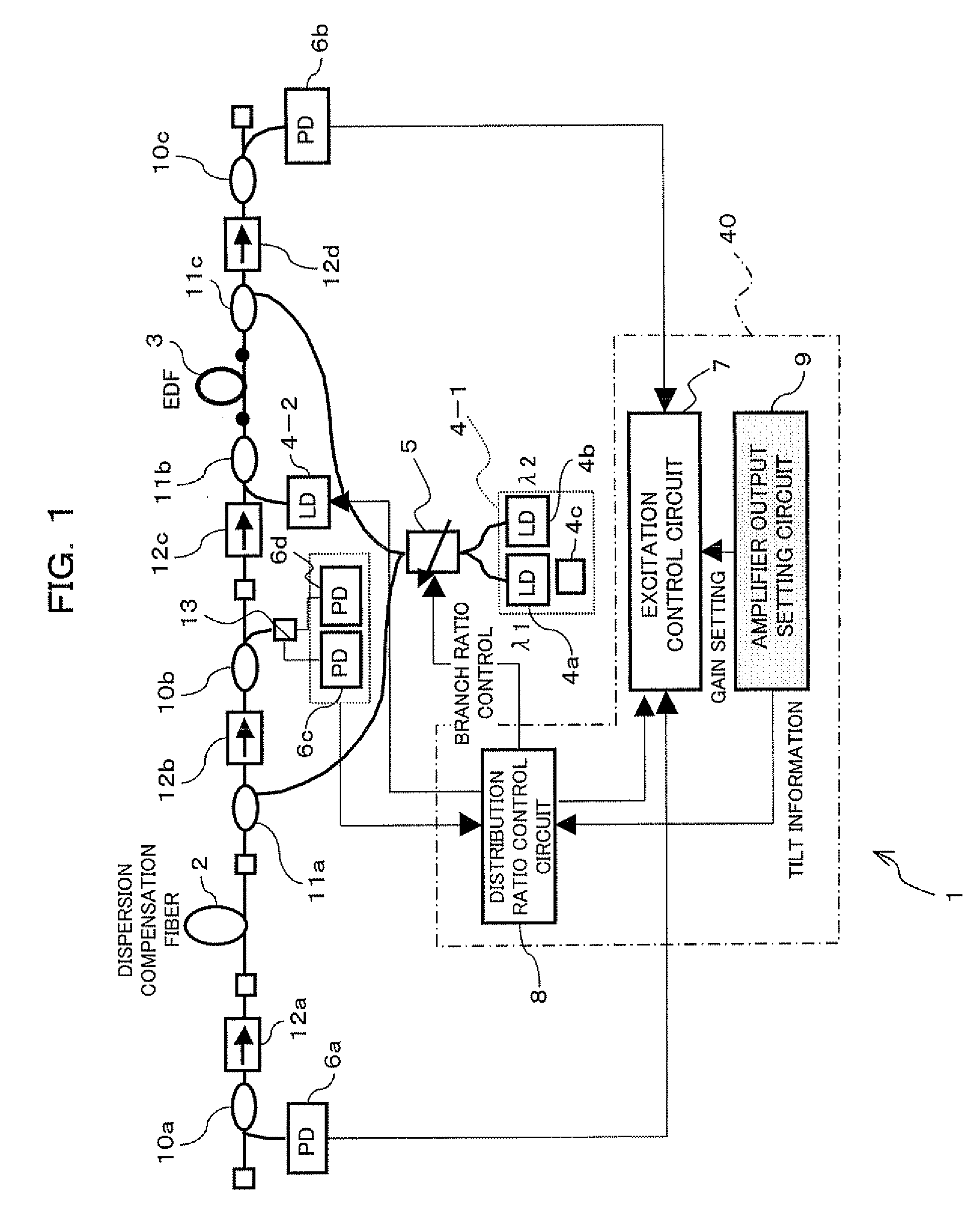
[0077]FIG. 1 is an illustration of an optical amplifier 1 according to a first embodiment of the present invention. In this optical amplifier 1, a dispersion compensation fiber (DCF) 2 which serves as a Raman amplification medium and an Erbium-doped optical fiber (EDF) 3 which is a rare earth doped fiber are cascade-connected to each other in this order from the signal input side, and the optical amplifier 1 further includes first and second pump light outputting units 4-1 and 4-2, a variable distribution element 5, PDs (Photo Diodes) 6a to 6d, an excitation control circuit (excitation control unit) 7, a distribution ratio control circuit (distribution ratio control unit) 8, an amplifier output setting circuit 9, branch couplers 10a to 10c, multiplexers 11a to 11c, optical isolators 12a to 12d and a wavelength filter 13.

[0078] The optical amplifier 1 according to the first embodiment is applicable as an optical amplification repeater in a WDM opti...

second embodiment

(b) Description of Second Embodiment

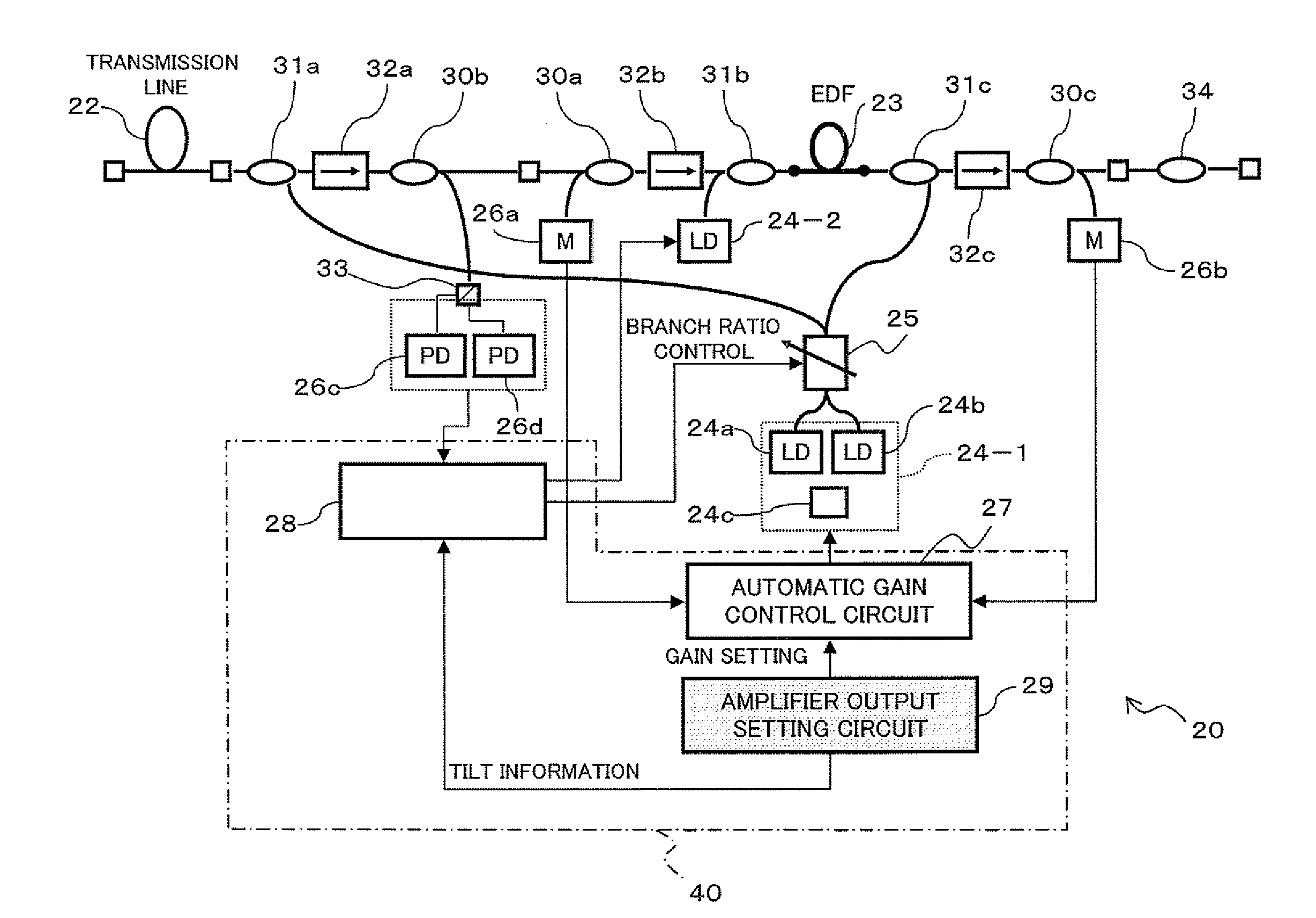
[0140]FIG. 9 is an illustration of an optical amplification repeater 20 according to a second embodiment of the present invention. This optical amplification repeater 20 shown in FIG. 9 is connected to a transmission line fiber 22 serving as an input side transmission line and a transmission line fiber 34 serving as an output side transmission line for repeating wavelength-multiplexed light, and it comprises an EDF 23, first and second excitation outputting units 24-1 and 24-2, LDs 24a and 24b, a level monitor 24c, a variable distribution element 25, PDs 26a to 26d, an excitation control circuit (excitation control unit) 27, a distribution ratio control circuit (distribution ratio control unit) 28, an amplifier output setting circuit 29, branch couplers 30a to 30c, multiplexers 31a to 31c and a wavelength filter 33 which respectively correspond to the components designated at reference numerals 3 to 9, 10a to 10c, 11a to 11c and 13 in the above-de...


PUM

PropertyMeasurementUnit
wavelengthaaaaaaaaaa
wavelengthsaaaaaaaaaa

Abstract

There is provided an optical amplifier including a Raman amplification medium, a rare earth doped fiber located at a latter stage of the Raman amplification medium, a first pump light outputting unit for outputting pump light with a plurality of wavelengths, a variable distribution element for distributing the pump light with the plurality of wavelengths, outputted from the first pump light outputting unit, to the Raman amplification medium and the rare earth doped fiber in a variable distribution ratio for each wavelength, and a control unit for individually controlling the distribution ratio of the pump light with the plurality of wavelengths in the variable distribution element and the power of the pump light with the plurality of wavelengths from the first pump light outputting unit in accordance with a wavelength arrangement of each of signal lights wavelength-multiplexed into the wavelength-multiplexed signal light.

Description

TECHNICAL FIELD [0001] The present invention relates to an optical amplifier, optical amplification repeater and pump light supply control method suitable for use in an optical transmission system. BACKGROUND ART [0002] An optical amplifier is for optically amplifying a signal directly to compensate for a loss occurring when an optical signal propagates in an optical fiber transmission path in an optical transmission system and further for losses in optical parts / optical modules, and it has an optical fiber medium for the optical amplification and an equipment for supplying pump light. This pump light supplying equipment supplies pump light with a predetermined wavelength to the optical fiber medium for the optical amplification, thereby placing the optical fiber medium into an activated state. The signal light is optically amplified and outputted when a signal is inputted to this optical fiber medium placed into the activated state. [0003] In a recent-year optical amplification rep...

Claims


Application Information

Patent Timeline
Patent Type & Authority Applications(United States)
IPC IPC(8): H01S3/30H01S3/00G02F1/35H01S3/067H01S3/10H01S3/23H04B10/29H04B10/294
CPCH01S3/06754H01S3/094003H01S3/2375H01S3/302H04B10/2916H01S3/1301H04B2210/003H04J14/0221H01S2301/04H01S3/10015H04B10/2942H01S3/094061H01S3/13013
Inventor MURO, SHINICHIROUSUGAYA, YASUSHIHAYASHI, ETSUKO
Owner FUJITSU LTD
Why Eureka
Try Eureka