Machine frame of cantilevered mode digital control flame plasma cutting machine

A plasma cutting machine and cantilever technology, applied in plasma welding equipment, gas flame welding equipment, welding/cutting auxiliary equipment, etc., can solve the problems of low control accuracy, inflexibility, affecting the use accuracy, etc., and achieve high repeatability , accurate positioning, reasonable design effect

Active Publication Date: 2008-11-05
无锡聚合科创发展有限公司
View PDF0 Cites 43 Cited by
  • Summary
  • Abstract
  • Description
  • Claims
  • Application Information

AI Technical Summary

Problems solved by technology

[0006] In traditional plasma cutting machines, the beam is generally made of cast iron, which is very heavy and inflexible in movement, poor in stability, low in control accuracy, and complicated to install
The beam and chassis of the traditional plasma cutting machine are fixed and cannot be rotated, so there are the following problems: 1. It occupies a large space during transportation and is inconvenient to transport; 2. During the transportation, the instability of the center will affect the Its future use accuracy; 3. It is troublesome to install and debug; 4. When the equipment is not in use, it will affect the work area space

Method used


Image

  • Machine frame of cantilevered mode digital control flame plasma cutting machine
  • Machine frame of cantilevered mode digital control flame plasma cutting machine

Examples


Embodiment Construction

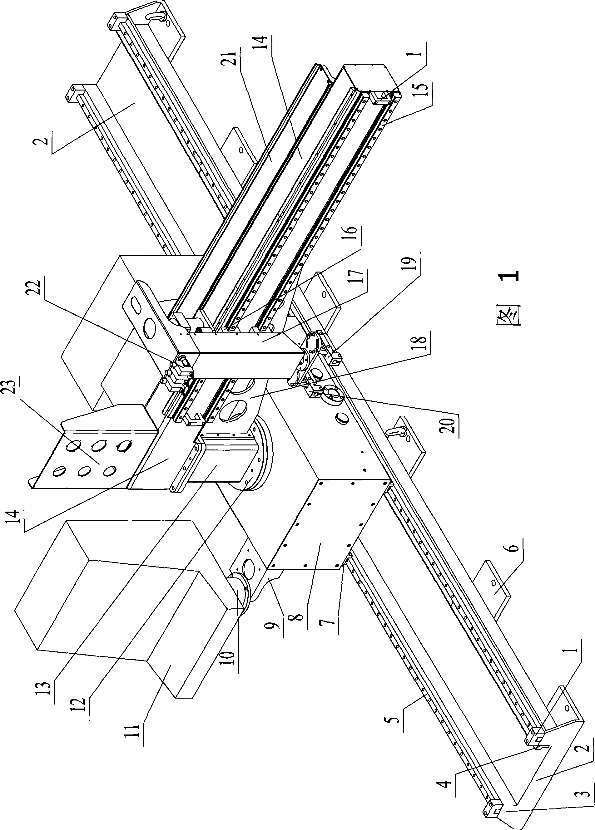
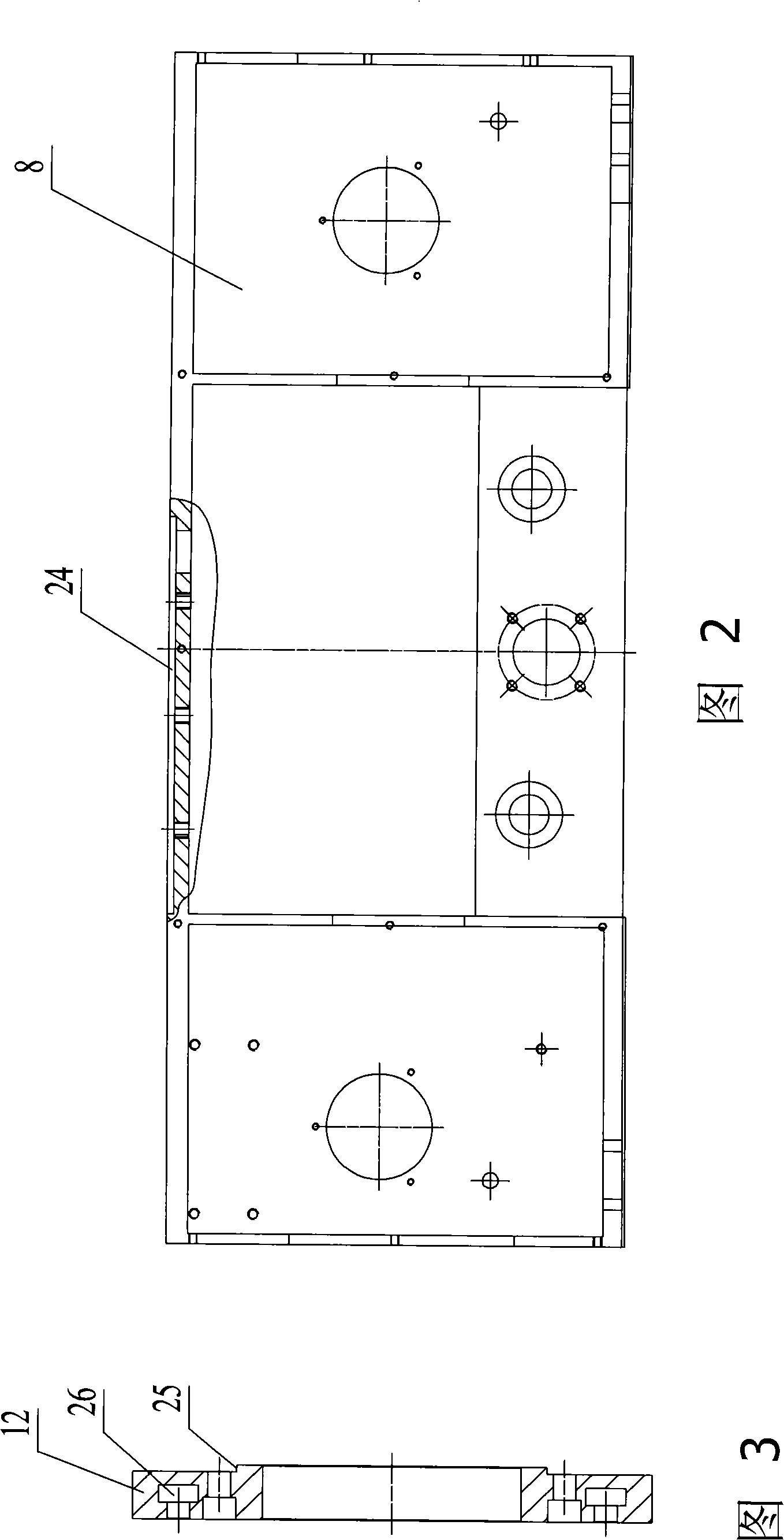
[0016] In the figure, 1. Block, 2. Machine base, 3. Underframe side sealing plate, 4. Inner reinforcement plate, 5. Longitudinal guide rail, 6. Base fixing plate, 7. Longitudinal slider, 8. Underframe, 9. System support frame, 10. System slewing ring, 11. System control box, 12. Turntable, 13. Column, 14. Cross arm, 15. Transverse guide rail, 16. Double-axis slider, 17. Lifting frame, 18. Support ribs.

[0017] As shown in the figure: there is a rotary disc 12 between the chassis 8 and the column 13, the bottom of the rotary disc 12 is connected to the chassis 8, the column 13 is connected to the upper part of the rotary disc 12; the upper part of the column 13 is connected Cross arm 14, transverse guide rail 15 is set on cross arm 14, on cross arm 14, the elevating frame 17 that can move on cross arm 14 is set, on elevating frame 17, transverse slide block 16 is set, and described transverse slide block 16 and The transverse guide rail 15 is slidably connected. The transver...


PUM


Abstract

The invention relates to a flame plasma cutting machine, in particular to a frame of the cantilever-typed numerical control flame plasma cutting machine. According to the technical proposal provided by the invention, a turning mechanism is arranged between an underframe and a vertical column; the bottom part of the turning mechanism is connected with the underframe; the vertical column is connected with the upper part of the turning mechanism; the upper part of the vertical column is connected with a transverse arm provided with a cross slide way; the transverse arm is provided with a lifting frame which can move on the transverse arm; the lifting frame is provided with a transverse sliding block connected with the cross slide way in a sliding way. The flame plasma cutting machine can facilitate the transportation and installation and improve the repeated precision and positioning angle.

Description

technical field [0001] The invention relates to a flame plasma cutting machine, in particular to a frame of a cantilever type numerical control flame plasma cutting machine. Background technique [0002] Plasma cutting is a processing method that uses the heat of the high-temperature plasma arc to locally melt or evaporate the metal at the incision of the workpiece, and uses the momentum of the high-speed plasma to remove the molten metal to form a cut. [0003] In plasma cutting, different working gases can be used to cut various metals that are difficult to cut with oxygen, especially for non-ferrous metals such as stainless steel, aluminum, copper, titanium, nickel, etc., the effect of plasma cutting is better; When cutting metal, the plasma cutting speed is fast. When cutting ordinary carbon steel sheets, the speed can reach 5-6 times that of the oxygen cutting method. The cutting surface is smooth, the thermal deformation is small, and there is almost no heat-affected z...

Claims


Application Information

Patent Timeline
Patent Type & Authority Applications(China)
IPC IPC(8): B23K37/00B23K28/02B23K10/00B23K7/10
Inventor 钱锡军
Owner 无锡聚合科创发展有限公司
Why Eureka
Try Eureka