Method for changing old simple supported beam bridge into continuous beam bridge

A technology of supported girder bridge and simply supported girder is applied in the field of transforming old simply supported girder bridges into continuous girder bridges, which can solve the problems of many expansion joints, inability to improve the rigidity of components, and frequent driving bumps.

Inactive Publication Date: 2008-11-05
SOUTHEAST UNIV
View PDF0 Cites 9 Cited by
  • Summary
  • Abstract
  • Description
  • Claims
  • Application Information

AI Technical Summary

Problems solved by technology

[0006] The invention aims at the disadvantages that the sticking reinforcement method cannot improve the stiffness of the components, and the secondary stress can only participate in the work. At the same time, it overcomes the defects of many expansion joints on the bridge deck of the multi-span long bridge and frequent driving bumps, etc., and provides a pre-stressing method in the negative bending moment area. The method of transforming the old simply supported girder bridge into a continuous girder bridge, so that the old simply supported reinforced concrete girder can continue to be used, and its bearing capacity and rigidity can be improved

Method used


Image

  • Method for changing old simple supported beam bridge into continuous beam bridge
  • Method for changing old simple supported beam bridge into continuous beam bridge
  • Method for changing old simple supported beam bridge into continuous beam bridge

Examples


Embodiment Construction

[0026] A method of converting an old simply supported girder bridge into a continuous girder bridge:

[0027] a. First chisel out the bridge deck concrete within the range where the old simply supported beams need to be connected,

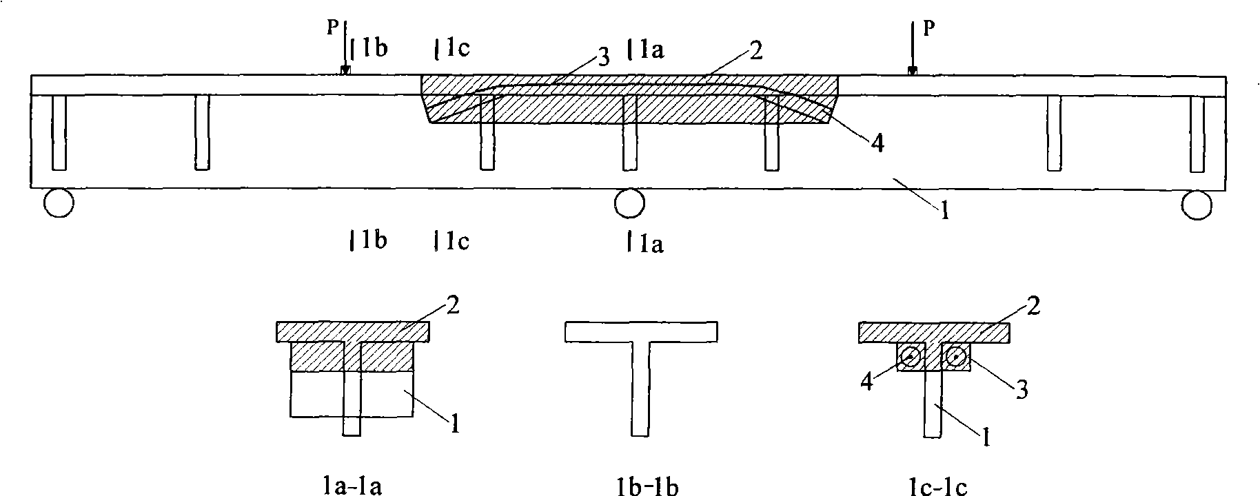
[0028] b. Set the tooth plate in the chiseled area of ​​the reinforced concrete T-beam and the tooth plate is located on both sides of the web, and the metal bellows is embedded in the tooth plate,

[0029] c. Pass the steel strand through the metal bellows, one end is anchored, and the other end is used as the tension end. The number of bundles of the steel strand is calculated and determined according to the predetermined prestress.

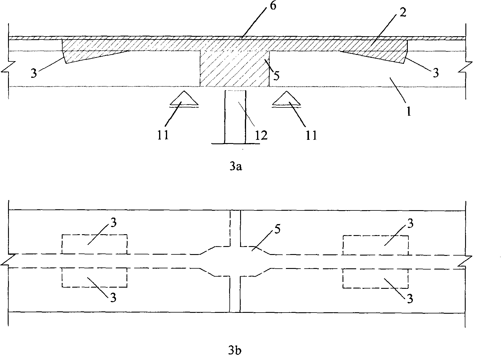
[0030] d. Widen the to-be-connected end of the T-beam, and install a diaphragm in the gap between the to-be-connected T-beams, pour concrete at the connected end and the bridge deck,

[0031] e. After the newly poured concrete reaches the design tensile strength, the steel strand is tensioned and anchored, and the ...


PUM


Abstract

The invention relates to a method for converting an old and simple supported girder bridge into a continuous girder bridge. The method includes the following steps: 1. the concrete of bridge faceplate in a required connecting scope of the old and simple supported girder is removed; 2. dental plates are arranged on removed zones of reinforced concrete T girders and are positioned on two sides of ventral shields, and metal corrugated pipes are pre-embedded in the dental plates; 3. stranded wires are threaded through the metal corrugated pipes and one end of the stranded wire is anchored and the other end is adopted as a tensioning end, and the quantity of bundles of the stranded wire is defined according to a pre-set pre-stress; 4. ends of T girders to be connected are widened and a diaphragm plate is arranged in a gap between T girders to be connected, and the connecting ends and bridge faceplate concrete are cast respectively; 5. after the newly-cast concrete reaches the designed tension strength, the stranded wires are stretched and anchored, and the pre-stress is transmitted to a hogging moment zone of the reinforced concrete I-beam girder through both new and old concretes. The method of the invention converts the old and simple supported girder bridge into the continuous girder bridge by bringing pre-stress to the hogging moment zone, which leads the old and simple supported concrete girders to be used continuously by enhancing the bearing capability and rigidity of the old concrete girders.

Description

technical field [0001] The invention relates to a method for longitudinally forming a continuous girder of an old simply supported girder bridge by applying prestress, in particular to a method for transforming an old simply supported girder bridge into a continuous girder bridge by changing the structural system for reinforcement. Background technique [0002] The simply supported reinforced concrete T-beam bridge is a bridge structure widely used in my country. After years of operation, under the influence of various external factors, the bearing capacity and stiffness of reinforced concrete T-beams can no longer meet the requirements of modern transportation. In recent years, the commonly used methods for strengthening old simply supported girder bridges include pasting steel plate method and pasting carbon fiber cloth method. Although the external reinforcement method is simple in construction, it has two major disadvantages: [0003] 1. The high-strength performance of...

Claims


Application Information

Patent Timeline
IPC IPC(8): E01D22/00E01D101/24
Inventor 王文炜翁昌年李淑琴李果
Owner SOUTHEAST UNIV
Why Eureka
Try Eureka