Cooling apparatus of scrapers

A cooling device and mechanical technology, applied in the direction of earth mover/shovel, construction, etc., can solve the problems of aggravated engine overheating, poor cooling effect, large wind energy loss, etc., to reduce the working pressure of the fan and ensure the air cooling effect. , the effect of reducing air resistance

Inactive Publication Date: 2008-11-05
SINOMACH CHANGLIN CO LTD
View PDF2 Cites 10 Cited by
  • Summary
  • Abstract
  • Description
  • Claims
  • Application Information

AI Technical Summary

Problems solved by technology

However, when the cooling fan speed is increased, the power consumed by the cooling fan is proportional to the third power of its speed, which further consumes the effective power of the engine and aggravates the overheating of the engine.
[0009] Another deficiency of the above-mentioned prior art is that it is difficult to clean when the air flow channel in the radiator is blocked
[0013] The disadvantages of the above-mentioned technical solution are: the structural setting of the intercooler, radiator and oil cooler is unreasonable, and the air cooling efficiency of the hydraulically driven fan is low
[0015] The disadvantage of the above-mentioned technical solution is that the cooling devices are arranged in three rows front and back, and when the fan is in front of the first row, when the fan performs suction cooling, the wind energy loss is large and the air passing through the three rows of cooling devices is always It is in a turbulent state (that is, the direction and speed of each particle of the air are constantly changing during the flow process, which are different), resulting in poor overall cooling effect and cannot meet the actual heat dissipation requirements.

Method used


Image

  • Cooling apparatus of scrapers
  • Cooling apparatus of scrapers
  • Cooling apparatus of scrapers

Examples


Embodiment 1

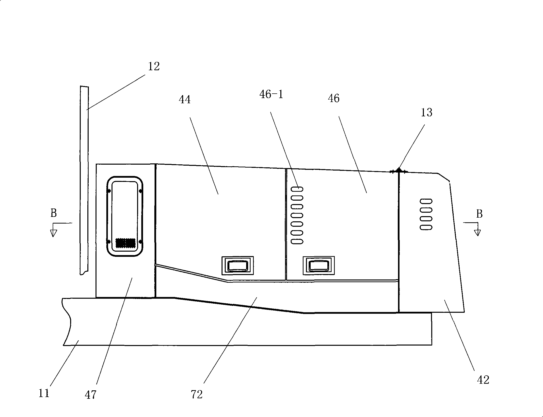
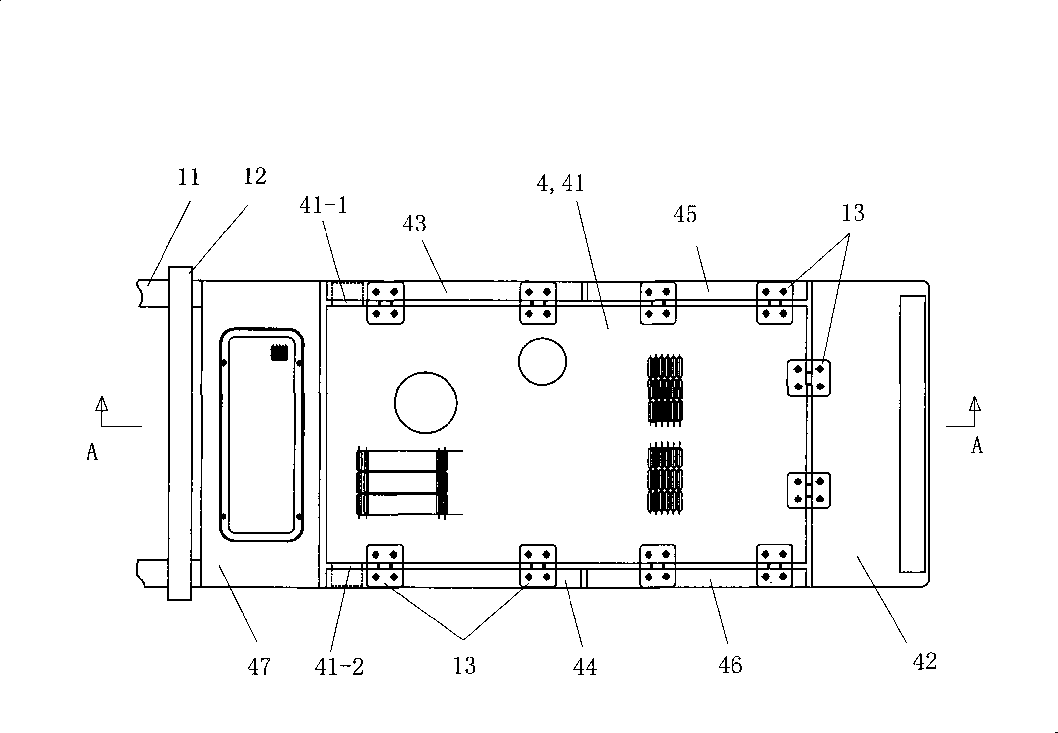
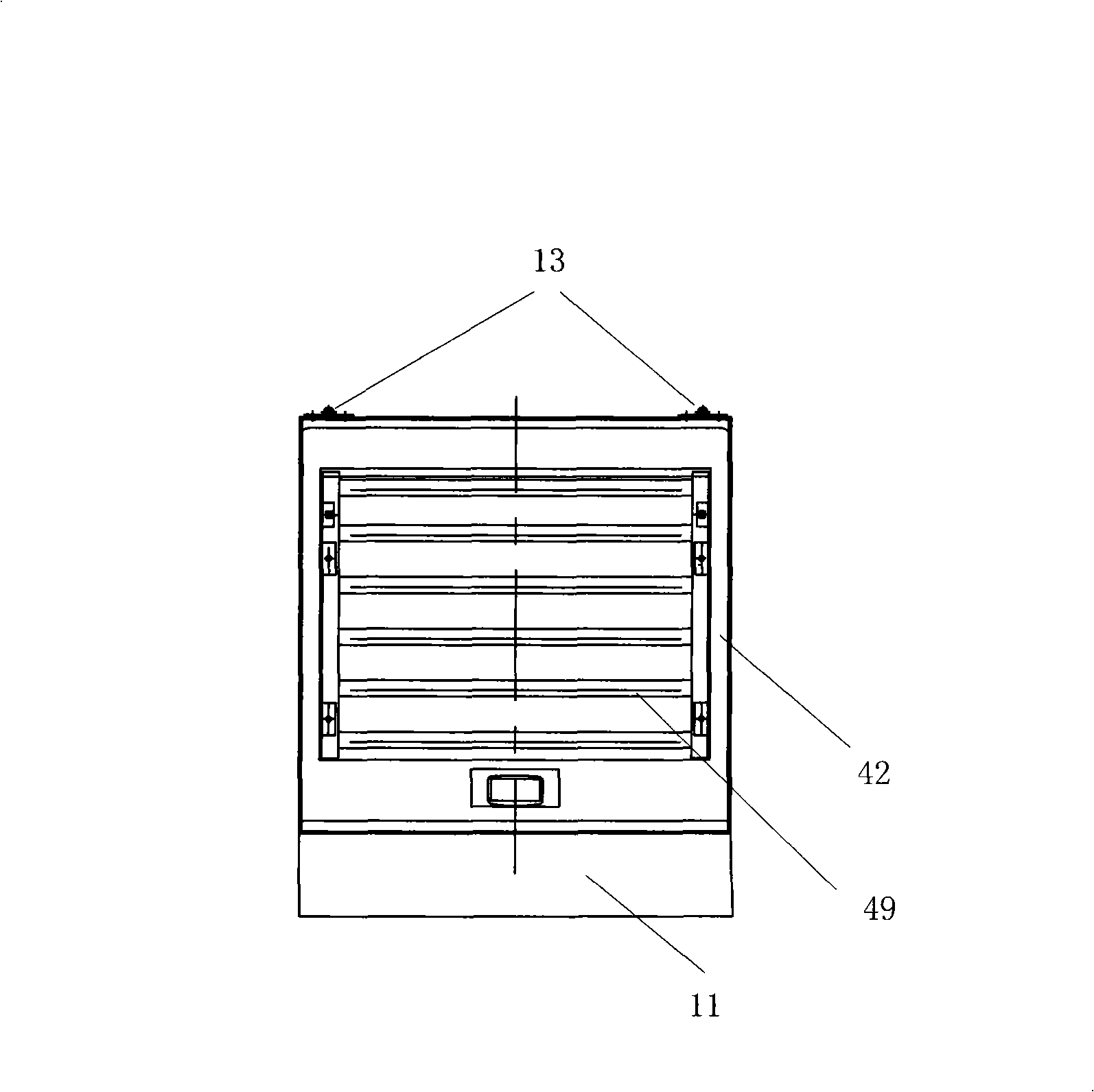
[0040] See Figure 1 to Figure 4 , the cooling device of the shoveling machine of the present embodiment is a cooling device of a loader or a grader, including a vehicle frame 11, a mounting frame 2, a heat shield 3, an outer cover 4, a water radiator 51, and an intercooler 52 , oil radiator 53 and cooling fan 54. The cooling fan 54 is a fan that sucks air from the back to the front during work.

[0041] still see Figure 1 to Figure 4 , the water radiator 51, the intercooler 52, the oil radiator 53, the cooling fan 54 and the heat shield 3 are located in the outer cover 2; Radiator 53 and cooling fan 54 are fixed on the mounting frame 2; Cooling fan 54 is fixed on the vehicle frame 11 by corresponding elastic support; Cooling fan 54, water radiator 51, intercooler 52 and oil radiator 53 The direction is set according to the front and rear three rows, the cooling fan 54 is located in the rear row, and is arranged at the tail of the vehicle frame 11; the water radiator 51 is...


PUM


Abstract

The invention relates to a cooling device of scooptram mechanism, comprising a vehicle frame, an outer cover, a cooling fan and a heat dissipating device. A mounting deck is fixed on the vehicle frame; the heat dissipating device is fixed on the mounting deck; each component of the heat dissipating device is arranged in three rows in fore-and-after direction; the cooling fan is positioned at the back row and installed at the tail part of the vehicle frame; a water radiator is positioned at the middle row; a charge air cooler and an oil radiator are positioned at the front row; thermal baffles are positioned in front of the charge air cooler and the oil heat radiator; the outer cover is installed on the mounting deck so that the outer cover and the thermal baffles as well as the space surrounded by both form a cooling chamber positioned at the back side of an engine and that the cooling fan, the water radiator, the charge air cooler and the oil radiator are positioned inside the cooling chamber. The cooling device of the invention is separated from an engine body via the cooling chamber, and the air draught is basically in the state of stable flowing when a suction cooling fan works; therefore, the structure reduces the air friction, reduces the working pressure of the fan and has better wind cooling effect.

Description

technical field [0001] The invention relates to a component of a scraper machine. Background technique [0002] Scrapers include loaders and motor graders. The cooling device of the loader or grader usually uses the radiator as a heat exchanger and cools the cooling water and high-pressure exhaust gas of the engine and the power oil and lubricating oil of the hydraulic system of the loader in an air-cooled manner. Among them, the component that cools the engine cooling water is the water radiator, the component that cools the high-pressure exhaust gas of the engine is the intercooler, and the component that cools the hydraulic oil and lubricating oil of the hydraulic system is the oil radiator. [0003] The function of the water radiator is: after the cooling water is pumped out by the water pump, it flows through the engine block to take away heat, then enters the water radiator for cooling, and then returns to the water pump for circulation. [0004] The role of the inte...

Claims


Application Information

Patent Timeline
Patent Type & Authority Applications(China)
IPC IPC(8): E02F9/00
Inventor 吴光耀王玉林包振义傅清栗利刚王秀芳
Owner SINOMACH CHANGLIN CO LTD
Why Eureka
Try Eureka