Supercharge Your Innovation With Domain-Expert AI Agents!

Rotating angular acceleration sensor

A technology of acceleration sensor and rotation angle, which is applied in directions such as acceleration measurement using inertial force, and can solve problems such as inability to measure rotation angular acceleration

Inactive Publication Date: 2010-12-08
JIAXING UNIV +2
View PDF3 Cites 0 Cited by
  • Summary
  • Abstract
  • Description
  • Claims
  • Application Information

AI Technical Summary

Problems solved by technology

The sensor is used to measure vibration acceleration, because its copper ring is connected to the shell, it cannot measure rotational angular acceleration

Method used


Image

  • Rotating angular acceleration sensor
  • Rotating angular acceleration sensor
  • Rotating angular acceleration sensor

Examples


Embodiment 1

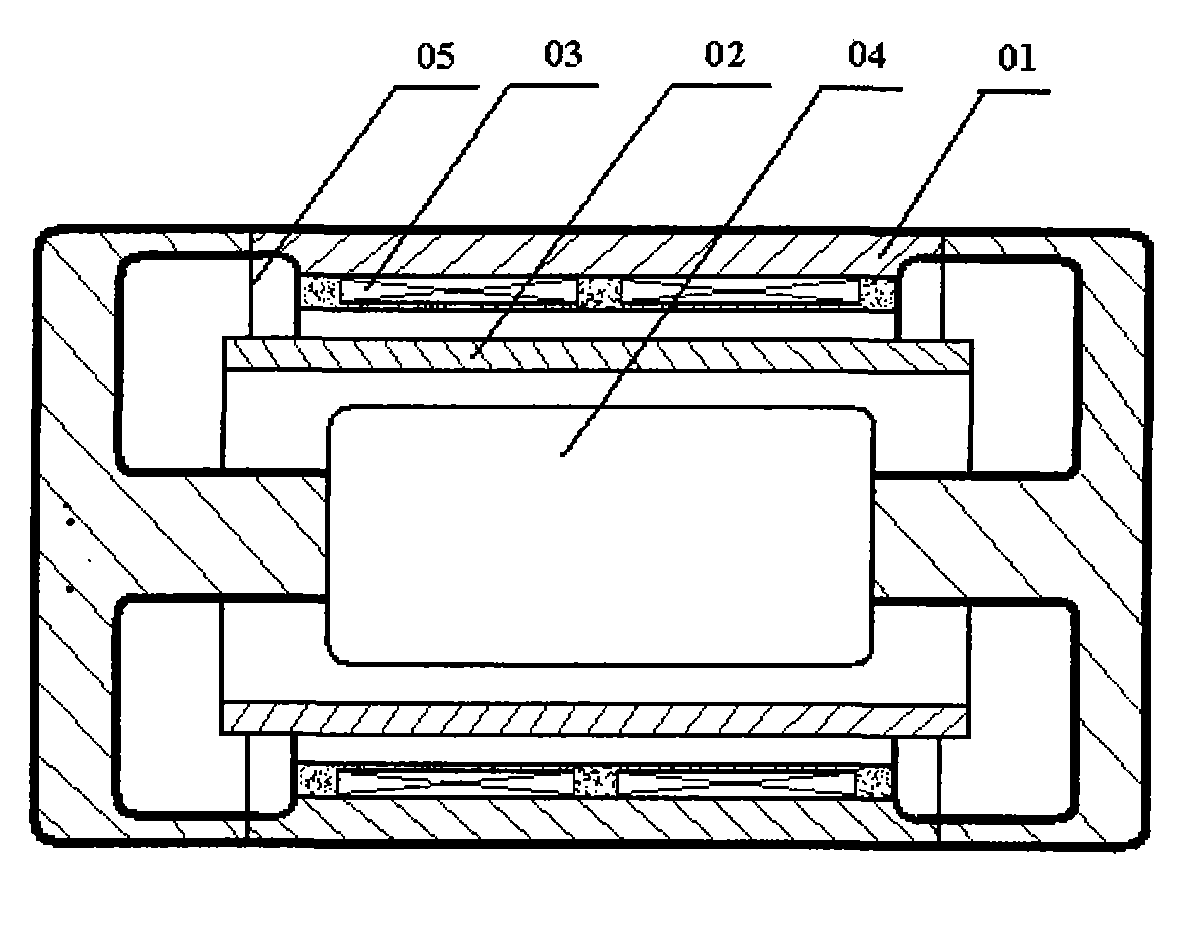
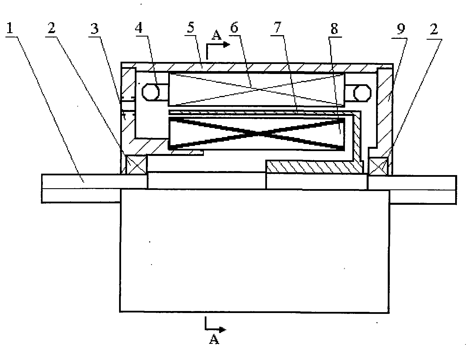
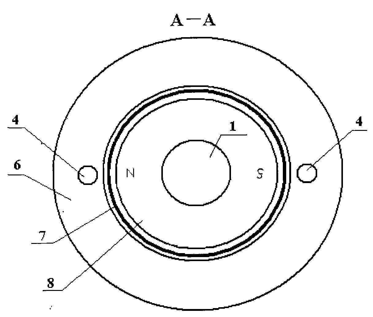
[0027] Embodiment 1: the structure of angular acceleration sensor is as figure 2 as shown, figure 2 The cross-sectional view of the A-A plane in the middle is as follows image 3 As shown, the excitation magnetic field is a permanent magnet structure: that is, the excitation magnetic field between the inner stator core 8 and the outer stator core 6 is a permanent magnet inner stator core composed of permanent magnet materials as the inner stator core 8 and the outer stator core 6. The excitation field formed by the exciter of the magnetic circuit. from image 3 It shows that the output winding 4 of the outer stator core is embedded in the winding slot of the outer stator core 6, and the axis of the output winding 4 of the outer stator core is perpendicular to the magnetic axis of the excitation field. The cup-shaped rotor winding 7 is located in the exciting magnetic field (air-gap magnetic field) between the inner and outer stator cores, and the outer stator core 6, cup-...

Embodiment 2

[0030] Embodiment 2: the structure of angular acceleration sensor is as figure 2 as shown, figure 2 The cross-sectional view of the A-A plane in the middle is as follows Figure 4 shown. The difference between embodiment 2 and embodiment 1 is that the excitation magnetic field is an electromagnetic structure. That is, the excitation magnetic field between the inner stator core 8 and the outer stator core 6 is powered by the outer stator core excitation winding 10 placed in the upper winding slot of the outer stator core 6 through a DC constant current source as the inner stator core 8 and the outer stator core 6 The excitation magnetic field formed by the excitation source of the magnetic circuit between them; Figure 4 As shown, the excitation winding 10 of the outer stator core and the output winding 4 of the outer stator core are embedded in the winding slot of the outer stator core 6, and the excitation winding 10 of the outer stator core excites the iron core through...


PUM


Abstract

A rotation angular acceleration sensor comprises an engine base; a front end cover and a back end cover which are respectively at the front end and back end of the engine base; a rotation shaft which traverses the centers of the front end cover and the back end cover; an external stator iron core which is coaxial with the rotation shaft and is provided in the engine base and is provided with a winding slot; an inner stator iron core which is provided between the external stator iron core and the rotation shaft and is coaxial with the external stator core and the rotation shaft, wherein an excitation field is provided between the inner stator iron core and the external stator iron core; an external stator iron core output winding which is provided in the winding slot on the external statoriron core; and a cup-shaped rotor winding which has a cup base installed on the rotation shaft and a cup body in the excitation field between the inner stator iron core and the external stator iron core. The rotation shaft of the system being measured is coaxially connected with the rotation shaft of the sensor which directly switches the rotation angular acceleration on the rotation shaft of thesystem being measured to the electrical signal for outputting. The outputted electrical signal is directly corresponding with the rotation angular acceleration. Correspondingly the sensor according to the invention has the advantages of higher measurement precision, simple structure and easy operation.

Description

technical field [0001] The present invention relates to an acceleration sensor, in particular to an angular acceleration sensor, and more particularly to a rotation angular acceleration sensor. Background technique [0002] In the control, monitoring and navigation of many moving objects, not only angular displacement and angular velocity information, but also angular acceleration information is required. The measurement of rotational angular acceleration is one of the common measurements in mechanical quantity measurement. The known measurement of rotational angular acceleration is generally obtained through indirect synthesis of several linear acceleration signals. There is also a liquid ring rotational angular acceleration sensor that uses the principle of streaming potential to directly measure the rotational angular acceleration, but the implementation is more complicated or the accuracy is relatively low. [0003] In the disclosed prior art, Chinese Utility Model Pat...

Claims


Application Information

Patent Timeline
Patent Type & Authority Patents(China)
IPC IPC(8): G01P15/08
Inventor 冯浩李洪武丁立军
Owner JIAXING UNIV
Features
  • R&D
  • Intellectual Property
  • Life Sciences
  • Materials
  • Tech Scout
  • Unparalleled Data Quality
  • Higher Quality Content
  • 60% Fewer Hallucinations
Learn More