
Electrostatic precipitator with high-efficiency dust collecting pole

A technology of electrostatic precipitator and dust collector, which is applied in the direction of electrode structure, electrostatic separation, electrode cleaning, etc. It can solve the problems of fixed area, low efficiency of dust removal, and secondary flying of dust, etc.

Active Publication Date: 2008-11-12
孟金来
View PDF0 Cites 37 Cited by
  • Summary
  • Abstract
  • Description
  • Claims
  • Application Information

AI Technical Summary

Problems solved by technology

There are many forms of dust collecting poles, there are two types: pull-type and tube-type, and pull-type electrodes are divided into three types: flat-shaped electrodes, box-type electrodes and plate-type electrodes. These dust-collecting poles have the following shortcomings: 1. Dust-collecting poles It is fixedly installed in the shell, and the dust collection and dust cleaning are carried out in the shell, so it is easy to generate secondary flying when cleaning the dust.
2. At present, the dust collectors are all made of steel plates in flat or corrugated shape, with a fixed area, and the orientation of the pole plates is consistent with the direction of the dust-laden airflow. Dust collection efficiency below 99.5%
3. The dust removal efficiency is low for dust with high specific resistance (the conductivity of dust is usually expressed by specific resistance)
4. The capture rate of fine dust less than 1μm is low

Method used


Image

  • Electrostatic precipitator with high-efficiency dust collecting pole
  • Electrostatic precipitator with high-efficiency dust collecting pole
  • Electrostatic precipitator with high-efficiency dust collecting pole

Examples


Embodiment Construction

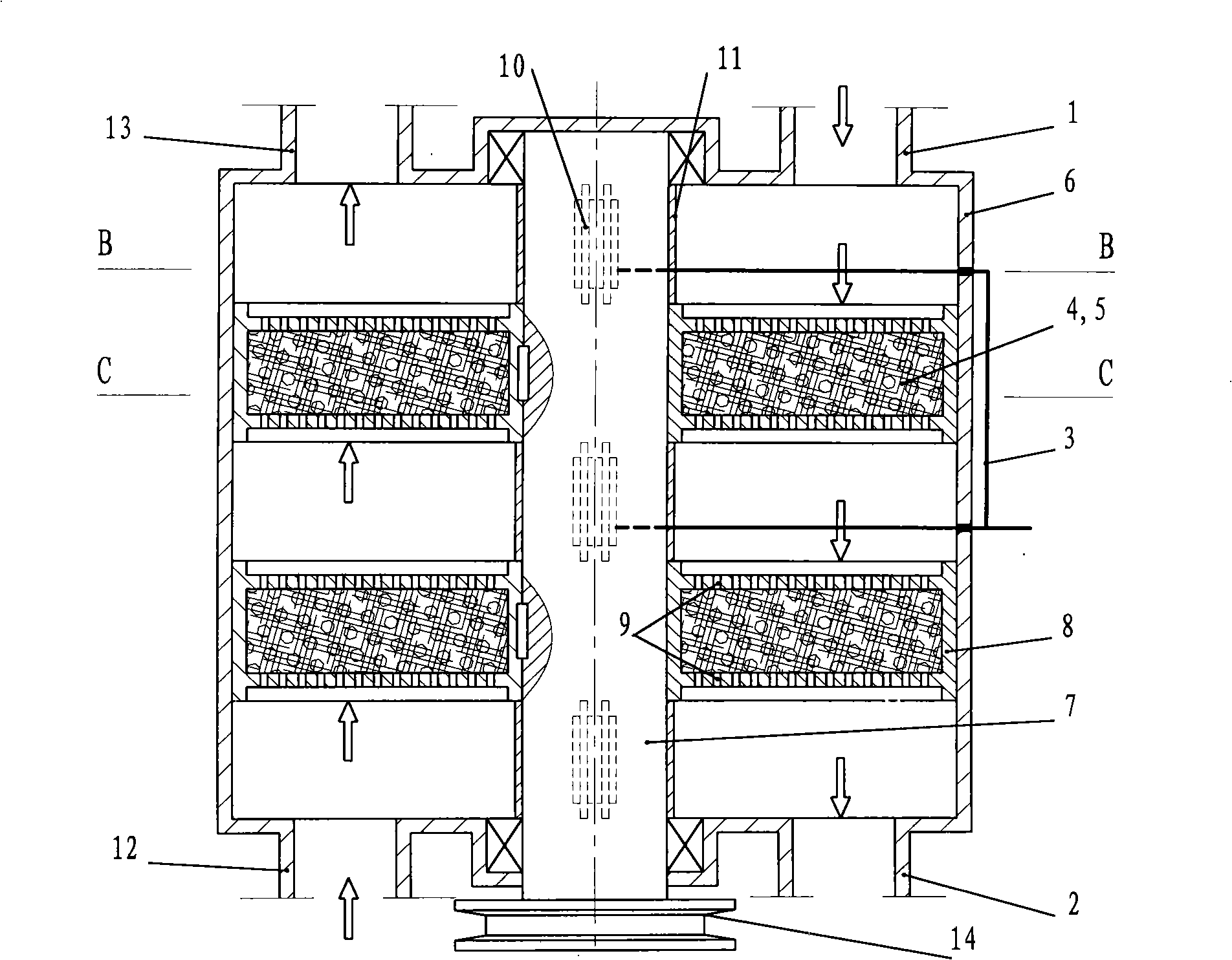
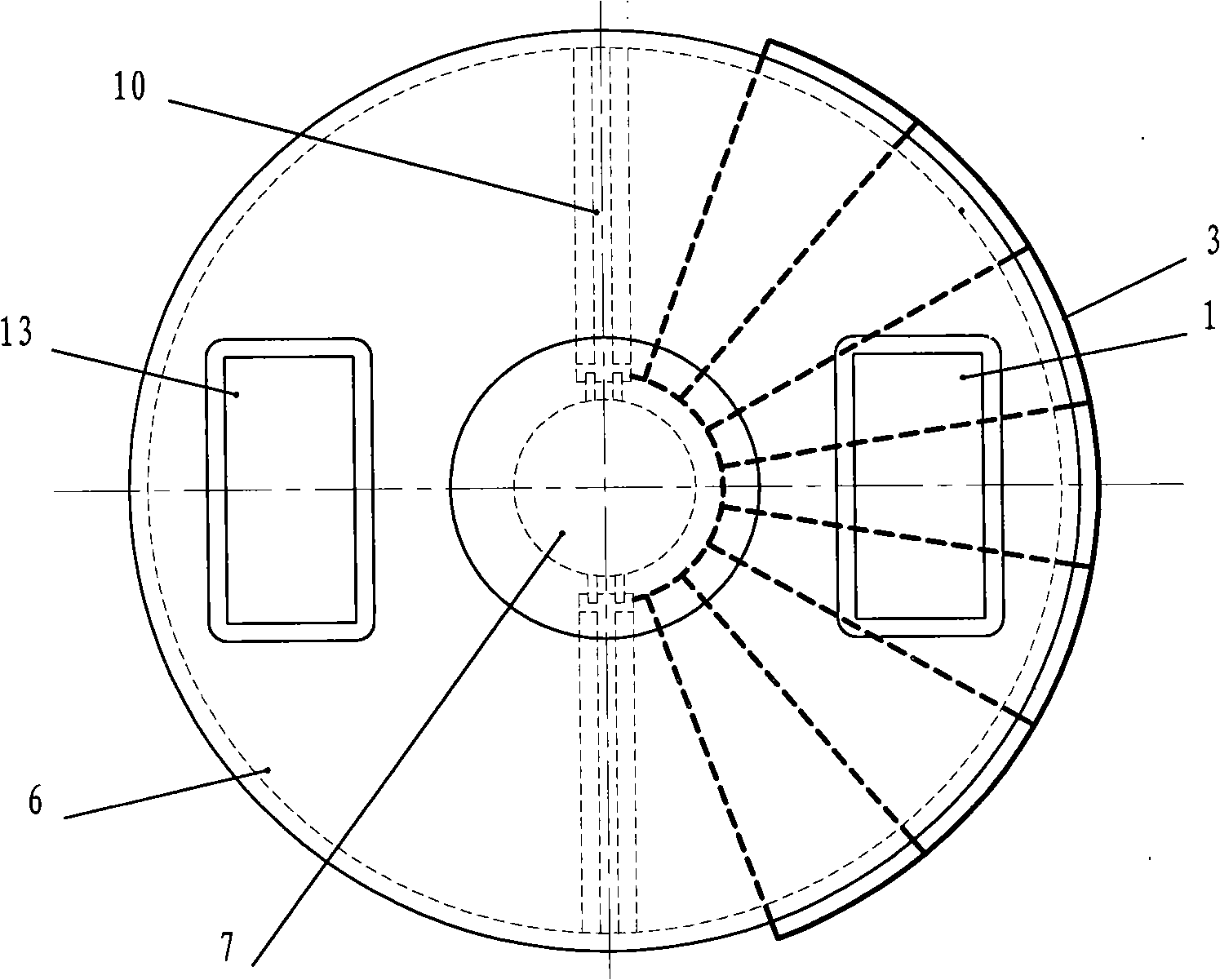
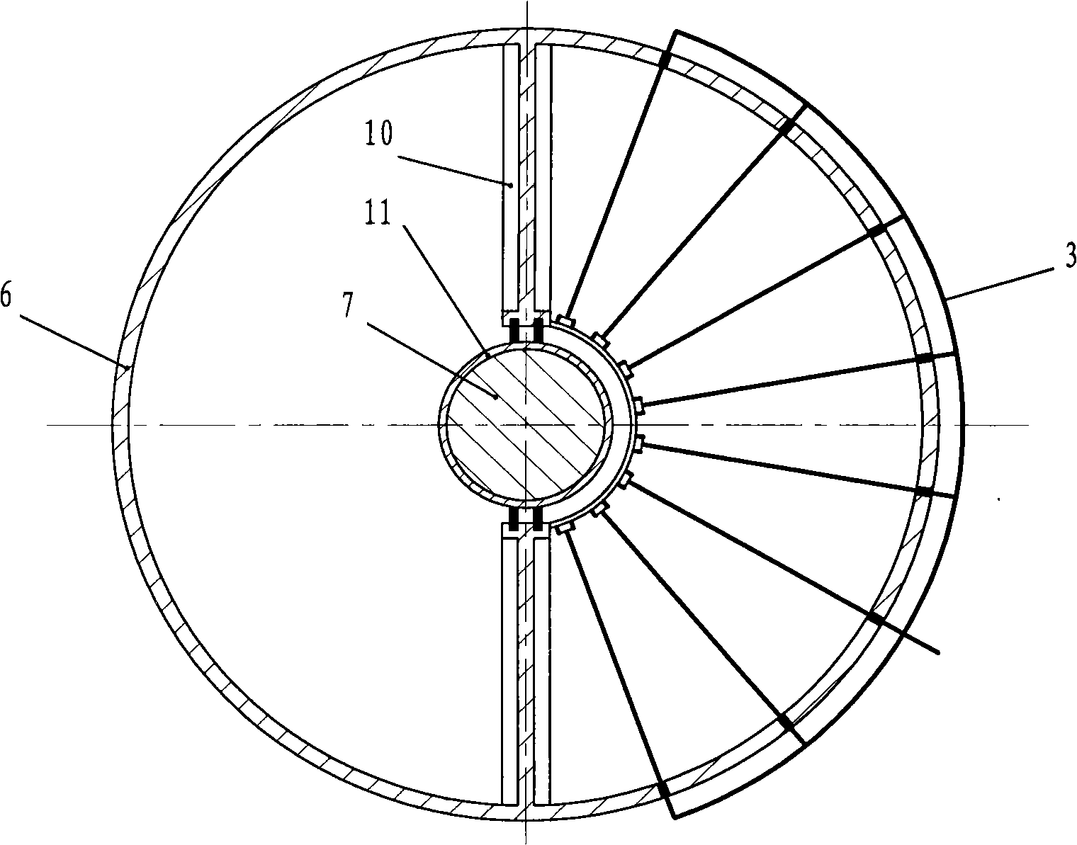
[0019] Depend on figure 1 Visible, the electric precipitator of efficient dust-collecting pole of the present invention comprises the housing that is provided with air inlet and outlet 1,2, discharge electrode 3 and dust-collecting pole are housed in the housing, and wherein dust-collecting pole comprises the hollowed-out metal casing and The shell is filled with a dust collection plate 4 or a dust collection ball 5 made of porous foam metal material or conductively treated porous foam plastic, and the dust collection plate 4 or dust collection ball 5 is placed in the integration room and the dust cleaning room movement between. According to this inventive idea, an electrostatic precipitator with three structures of dust collecting poles, namely rotary type, flat screen rotating curtain type and circulating flow type, has been designed.

[0020] Figure 1 ~ Figure 4 It is a schematic cross-sectional schematic diagram of the principle of an electrostatic precipitator with a r...


PUM


Abstract

The invention relates to an electrostatic precipitator of an efficient dust collecting electrode, comprising a shell which is provided with an airflow inlet and an airflow outlet. A discharge electrode and a dust collecting electrode are arranged in the shell. Wherein, the dust collecting electrode comprises a hollowed-out metal shell, and a dust collecting plate or a dust collecting sphere or an alveolar porous plate which is filled in the shell and manufactured by porous metallic foams or porous foam plastics processed via conductive treatment, and the dust collecting plate or the dust collecting sphere moves between an integration chamber and a dust cleaning chamber. The electrostatic precipitator of the efficient dust collecting electrode of the invention selects the porous metallic foams or the porous foam plastics processed conductive treatment, to manufacture a flat type, a granular type or an alveolar porous type to fill in the shell of a metal framework or a reticular formation to manufacture the dust collecting electrode with different structures such as rotary type, flat brattice type, circular flow type and so on, and at the same time separates a dust collecting area and a dust cleaning area to make dust collection efficiency of the electrostatic precipitator reach to more than 99.99%. The dust collecting electrode of the invention is particularly applicable to the last stage of the electrostatic precipitator, wherein, after dust abatement, dust content of the gas per cubic meter is less than or equal to 10mg.

Description

technical field [0001] The invention relates to an electric precipitator, specifically designs a brand-new, high-efficiency dust collecting electrode, and belongs to the technical field of separating dispersed particles from gas by electrostatic effect. Background technique [0002] The electrostatic precipitator uses the strong electric field generated by the high-voltage DC power supply to ionize the electronegative gas in the flue gas to generate a corona discharge, and then makes the dust suspended in the gas charged to reach the electrode with the opposite polarity under the action of the electric field force. On, so as to achieve the purpose of separating the suspended dust from the gas. Obviously, the electrostatic precipitator must have a discharge electrode and a dust collection electrode for collecting dust. At present, electrostatic precipitators are widely used, and there are many varieties and models; the structure of the dust collector directly affects the dus...

Claims


Application Information

Patent Timeline
IPC IPC(8): B03C3/45B03C3/78
Inventor 孟金来
Owner 孟金来
Learn More