Non-counterweight elevator system

An elevator system without counterweight technology, which is applied to elevators, elevators, transportation and packaging in buildings, etc., can solve the problems of waste of resources, optimal cost, heavy counterweight, etc., to save materials, ensure traction capacity, The effect of weight reduction

Active Publication Date: 2010-10-13
XIZI OTIS ELEVATOR
View PDF1 Cites 0 Cited by
  • Summary
  • Abstract
  • Description
  • Claims
  • Application Information

AI Technical Summary

Problems solved by technology

[0004] 1. From an economic point of view, on the one hand, it is necessary to accommodate conventional counterweights to move in the hoisting room, so extra space needs to be designed in the hoisting room, resulting in a waste of resources; on the other hand, in order to achieve the maximum To achieve balance, the weight of the counterweight remains constant no matter how the load changes. It is usually composed of the weight of the car system itself plus half the weight of the maximum load, which makes the weight of the counterweight itself heavy and high in cost; third, The rails used to guide the counterweight and the installation, labor and time-related costs involved in assembling these components
[0005] 2. From the perspective of traction capacity, in order to reduce the requirements for traction capacity, the closer the ratio of T1 / T2 is, the better. Usually, the formula for calculating the force on the heavy side is: T1=(P+Q) / 2, T2=(P+0.5Q) / 2, in the case of no load in the car system, to make the ratio of T1:T2 small, it is necessary to require the weight of the car system to be as heavy as possible, because the weight of the counterweight is usually determined by the car The weight of the system itself is composed of half the weight of the maximum load, which requires an increase in the weight of the counterweight, so that there is a contradiction between the traction capacity, the lightest car system, and the optimal cost
[0006] 3. From the perspective of energy, since the current elevator system can never achieve complete balance on both sides, only when the load reaches 50%, the energy consumption is the smallest, regardless of whether the load is 0% or 100%. The average power consumption reaches the maximum value, and elevators with high frequency of use are usually not near the 50% load condition, so the energy cannot reach the optimal configuration
But it has not really solved the three problems mentioned above, and has great limitations.

Method used


Image

  • Non-counterweight elevator system
  • Non-counterweight elevator system
  • Non-counterweight elevator system

Examples


Embodiment Construction

[0027] The technical contents and embodiments of the present invention will be further described below in conjunction with the accompanying drawings. It should be noted that the drawings and embodiments of the present invention are not intended to limit the technical solution of the present invention.

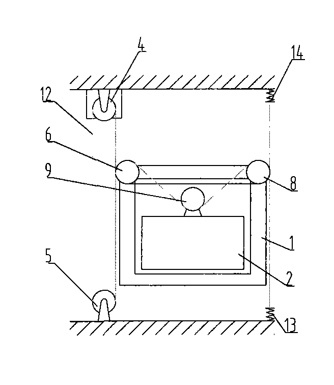
[0028] attached figure 1 A schematic diagram showing the structure of the prior art. See attached figure 1 You can clearly see the elevator system structure commonly used in the elevator industry at present, which includes: integral elevator car, car top wheel, pulley, traction rope and traction sheave, tensioning device and counterweight, etc., with structural It is complex, consumes a lot of energy, takes up a lot of space in the hoistway, and requires high man-hours and production costs.

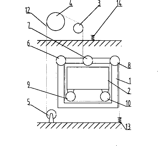
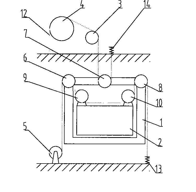
[0029] attached figure 2 Represent the structural representation of a preferred embodiment of the present invention, the non-counterweight elevator system of the present invention, com...


PUM


Abstract

The invention relates to a counterweight free lift system, which includes a car lifted in a shaft, a drive device, a hoisting rope and a hoisting rope wheel, and a plurality of pulleys, and is characterized in that: the car is a split-typed structure and uses body weight and load weight of the car as the counterweight to realize up-and-down motion of the car by the hoisting rope, a plurality of pulley rooms and one of the winding modes, wherein, at least two pulleys are arranged fixedly at two sides and the middle part on the upper part of the car frame, at least one pulley is fixed on the upper part of the body, the pulleys and the hoisting rope wheel are reciprocally vertical and correspondingly arranged on the upper part or the lower part of the shaft, one end of the hoisting rope is fixed at the fixing position on the upper part of the shaft, after winding the pulleys fixed on the car frame and the body in sequence, the terminal of the hoisting rope is fixed at the fixing positionon the lower part of the shaft. The invention does not require counterweight, which is an ideal lift product with economy, energy saving and novel and unique design.

Description

technical field [0001] The invention relates to a non-counterweight elevator system, specifically a kind of elevator car that does not need counterweight or counterweight, uses the weight of the elevator car itself and the weight carried by it as the counterweight, and realizes the lifting of the elevator car by surrounding the pulley with steel cables. up and down. Background technique [0002] The elevator system usually consists of a car system and a counterweight system that move up and down in the hoistway (hoist room). figure 1 is a schematic diagram of the prior art structure, figure 1 Indicates that the usual car is an integrated structure composed of two parts, the car frame 1 and the box body 2, where the box body 2 is supported by the car frame 1; the usual elevator system includes an elevator car, a driving device (traction machine) , traction rope (wire rope) and counterweight (counterweight); wherein the traction rope or other load-bearing parts move along pu...

Claims


Application Information

Patent Timeline
Patent Type & Authority Patents(China)
IPC IPC(8): B66B11/02B66B11/04B66B7/06
Inventor 张国华
Owner XIZI OTIS ELEVATOR
Why Eureka
Try Eureka