Hollow carcass for cast-in-situ concrete stuffing

A hollow carcass, cast-in-situ concrete technology, which is applied to floors, building materials, building components, etc., can solve the problems of inconvenient assembly line production, low production efficiency, inconvenient production, etc., and achieves simple design, simple construction, and fast construction speed. Effect

Inactive Publication Date: 2008-11-12
湖南邱则有专利战略策划有限公司
View PDF2 Cites 0 Cited by
  • Summary
  • Abstract
  • Description
  • Claims
  • Application Information

AI Technical Summary

Problems solved by technology

However, this kind of building components is inconvenient to manufacture, the production efficiency is low, it is not convenient for assembly line production, and the corresponding cost is high

Method used


Image

  • Hollow carcass for cast-in-situ concrete stuffing
  • Hollow carcass for cast-in-situ concrete stuffing
  • Hollow carcass for cast-in-situ concrete stuffing

Examples


Embodiment Construction

[0071] The present invention will be further described below in conjunction with the accompanying drawings and embodiments.

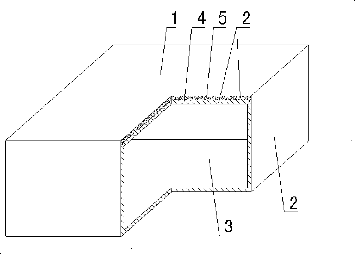
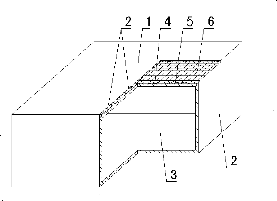
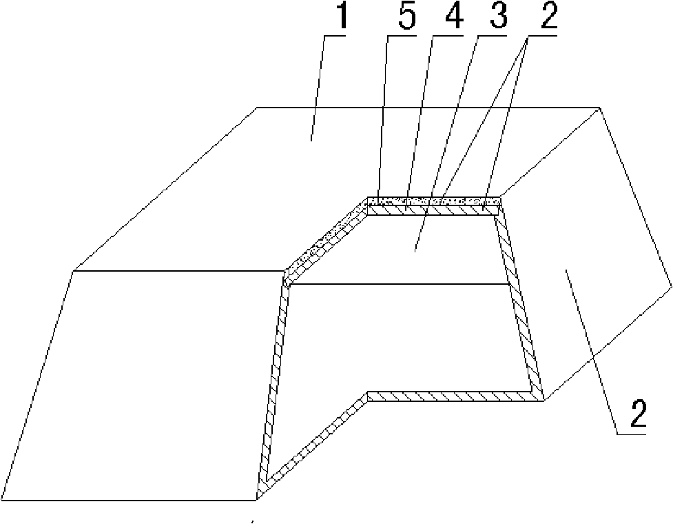
[0072] As shown in the accompanying drawings, the present invention includes a hollow carcass 1, which is formed by an outer wall 2 and has a cavity 3 inside, and is characterized in that the upper or lower outer wall 2 is a prefabricated board wall 4 and a slurry embryo body 5 The upper or lower outer wall 2 is a prefabricated board wall 4 and the slurry embryo body 5. The inner hard and the outer soft are laminated and cemented. In the accompanying drawings, 1 is the hollow carcass, 2 is the outer wall, 3 is the cavity, 4 is the prefabricated board wall, and 5 is the slurry body. In the following drawings, those with the same number have the same description. Such as figure 1 As shown, the hollow carcass 1 is formed by enclosing the outer wall 2, and there is a cavity 3 inside. The upper outer wall 2 of the hollow carcass 1 is a prefabricated board w...


PUM


Abstract

This invention discloses a hollow matrix used for filling field casting concrete, which comprises the hollow matrix (1) which is formed by the enclosing of an outer wall (2) and internally provided with a cavity (3); the hollow matrix is characterized in that the upper part or the lower part of the outer wall (2) is made by the soft and hard superposition, cementation and hardening of a precast batten wall (4) and a slurry billet (5); the upper part or the lower part of the outer wall (2) is made by the superposition, cementation and hardening of the precast board wall (4) and the slurry billet (5) with hard interior and soft exterior. The hollow matrix is applicable to field casting reinforced concrete or prestressed reinforced concrete hollow slabs, floors, roofs, wall bodies, foundation base plates and bridges, and is especially hollow girderless floors.

Description

[0001] This application is a divisional application of an invention patent application with an application date of August 11, 2004, an application number of 200410155218.0, and a title of "a hollow matrix for filling cast-in-place concrete". (1) Technical field [0002] The invention relates to a hollow matrix for filling cast-in-place concrete. (2) Background technology [0003] At present, the cast-in-place concrete hollow floor is a widely used floor structure. The lightweight permanent tire molds filled in it include various hollow tubes and boxes, and the boxes are hollow or solid. For example, the patent No. ZL99249798.1, which the applicant applied for on November 29, 1999, is a utility model patent named "fiber-reinforced thin-walled member for reinforced concrete filling", which discloses a thin-walled formwork member, including an upper plate, The surrounding side walls, the lower bottom, and the upper plate, the surrounding side walls and the lower bottom form a p...

Claims


Application Information

Patent Timeline
IPC IPC(8): E04C1/00E04C1/39E04C1/40E04B5/36E04B5/18
Inventor 邱则有
Owner 湖南邱则有专利战略策划有限公司
Why Eureka
Try Eureka