Quick plugging device
An occluder and fast technology, applied in the field of occlusion equipment, can solve the problems of increased cost, long time consumption, and extensive coverage of oil and gas well exploitation, shortened time to reach scope and pollution, reduced resource loss, convenient and reliable use Effect
- Summary
- Abstract
- Description
- Claims
- Application Information
AI Technical Summary
Problems solved by technology
Method used
Image
Examples
Embodiment 1
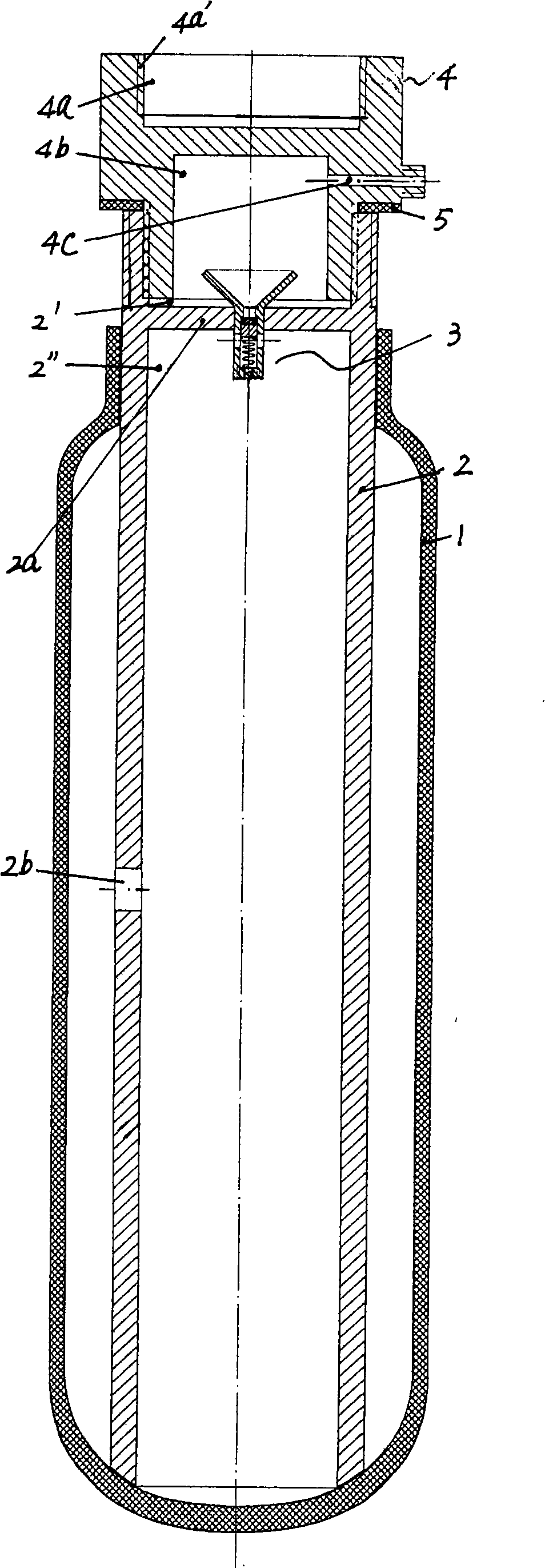
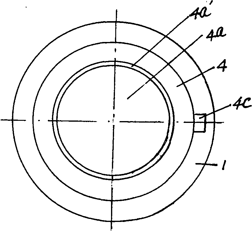
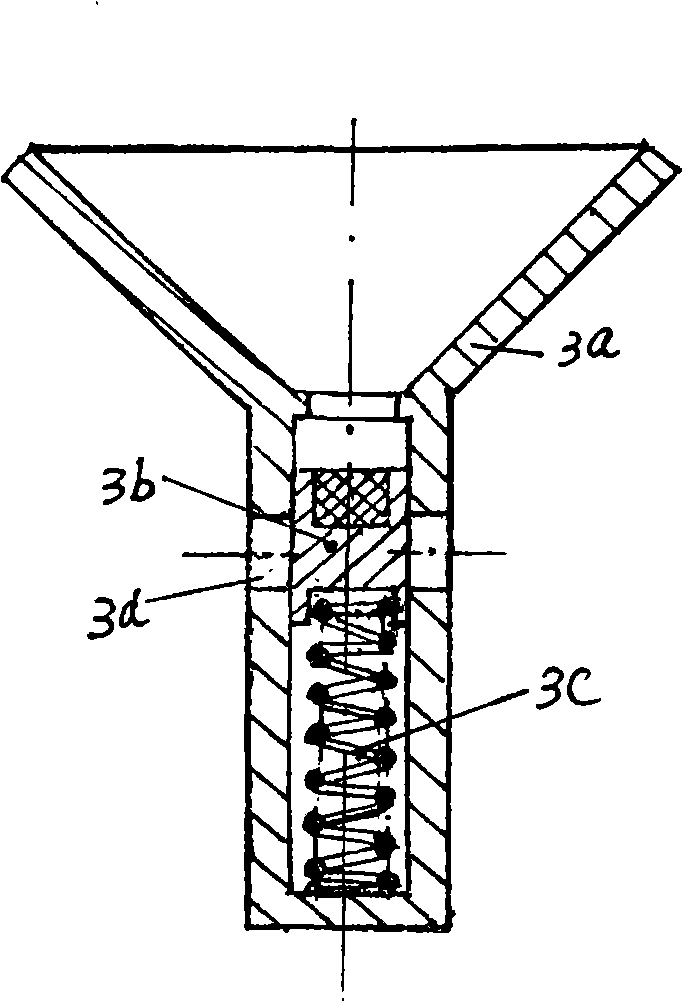
[0012] Embodiment 1, the quick occluder of the present invention, its structure can be from Figure 1 to Figure 4 As can be seen in the figure, it includes an airbag 1 with a tightened open end that can expand when pressurized and can automatically restore its original shape by its own elasticity when decompressed, an airbag that is inserted into the airbag and connected through the elastic seal of the airbag itself. The steel pipe 2 on the tightening end of the airbag, a space in the steel pipe 2 can be divided into a partition plate 2a that does not communicate with each other, an upper space 2' and a lower space 2 ", and a pressure supply that is fixed on the partition plate 2a The gas enters the one-way valve 3 from the upper space 2' of the steel pipe into the lower space 2". On the side wall of the steel pipe where the airbag space is located, a gas hole 2b that can communicate with the lower space 2" of the steel pipe and the airbag space is provided. Extending upward, t...
Embodiment 2
[0017] Embodiment 2, the structure of the rapid occluder of this embodiment can be obtained from Figure 5 ~ Figure 7See in, and embodiment 1 difference is: the joint that steel pipe 2 is threaded on the air bag extension end is a deflation joint 4 '. The joint is the same as the intake joint 4 in Embodiment 1: it also has an upper notch 4a and a lower notch 4b in its cross section, wherein the upper notch 4a also has a There is a vent 4c for pressurized gas on the side wall of the threaded interface 4a' that the tool is connected to, and the lower notch; the difference from Embodiment 1 is that the lower notch 4b of the deflation joint 4' in this embodiment is also There is a thimble 4d that can push back the one-way valve 3 to implement airbag deflation when the deflation joint 4' is connected to the steel pipe 2; the thimble is fixed on the partition between the upper and lower notches Below, its location matches where the check valve is located. Therefore, when the defla...
Embodiment 3
[0021] Embodiment 3, the rapid occluder of this embodiment, its structure can be from Figure 5 ~ Figure 7 Seen in, it differs from embodiment 2 in that: the deflation joint 4' also has a circle of guide ring 4e that can ensure that the joint is accurately docked with the steel pipe. It is convenient for people to carry out the air bag emptying operation above the wellbore with a high distance from the geologically tight rock layer, and the light in the wellbore is extremely dim.
[0022] After withdrawing the quick plugger, if you want to use the well, you can continue to drill; if you want to abandon the wellbore, you can directly seal the wellbore with heavy mud or concrete. If it is not used for the time being, you can also connect the steel pipe on the expansion air bag, and seal it with concrete around the steel pipe; Therefore, whether the occluder of the present embodiment is restored to the wellbore or not, or to resume use at any time later provides convenience.
PUM
 Abstract
Description
Claims
Application Information
 - R&D
- Intellectual Property
- Life Sciences
- Materials
- Tech Scout
- Unparalleled Data Quality
- Higher Quality Content
- 60% Fewer Hallucinations
Browse by: Latest US Patents, China's latest patents, Technical Efficacy Thesaurus, Application Domain, Technology Topic, Popular Technical Reports.
© 2025 PatSnap. All rights reserved.Legal|Privacy policy|Modern Slavery Act Transparency Statement|Sitemap|About US| Contact US: help@patsnap.com


