Pixel circuit and display device

A pixel circuit and pixel technology, applied in circuits, lighting devices, electric light sources, etc., can solve the problems of large volume, difficult high-definition display devices, etc., and achieve the effect of reducing leakage current

Inactive Publication Date: 2008-11-12
SONY CORP
View PDF2 Cites 7 Cited by
  • Summary
  • Abstract
  • Description
  • Claims
  • Application Information

AI Technical Summary

Problems solved by technology

The simple matrix display device has a simple structure, but has the problems of large volume and difficulty in realizing a high-definition display device

Method used


Image

  • Pixel circuit and display device
  • Pixel circuit and display device
  • Pixel circuit and display device

Examples


Embodiment Construction

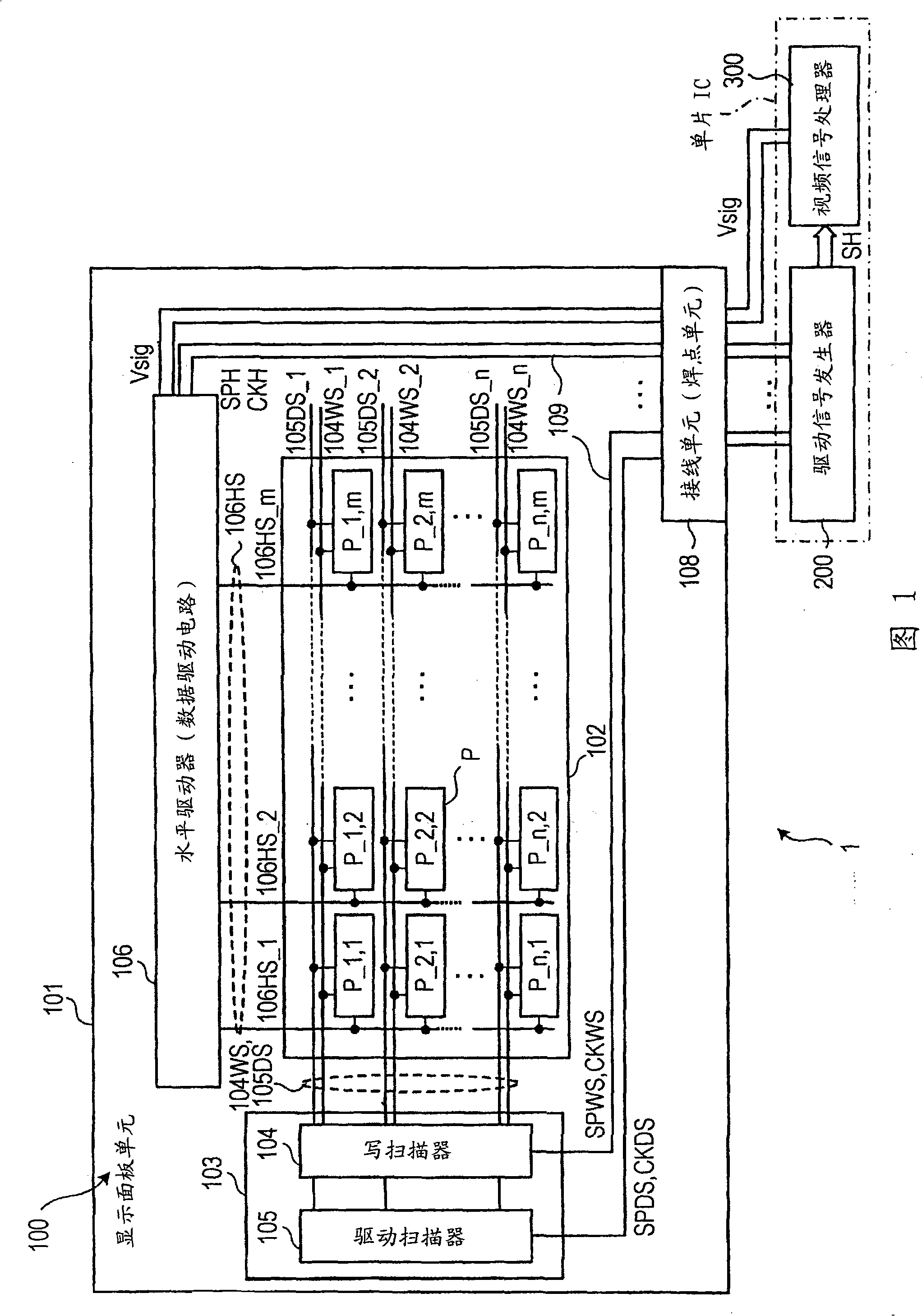
[0035] FIG. 1 is a schematic block diagram showing the structure of an active matrix display device that can be a display device according to an embodiment of the present invention. The embodiments will be described in the case of an active matrix organic EL display (hereinafter referred to as "organic EL display device") including a display element including an organic EL element as a pixel and a polysilicon thin film transistor (TFT) as an active element, Among them, as an example, an organic EL element is formed on a semiconductor substrate on which TFTs are formed.

[0036] Referring to FIG. 1 , an organic EL display device 1 includes a display panel unit 100 . The display panel unit 100 includes a pixel circuit (hereinafter also referred to as a "pixel") P having a plurality of organic EL elements (not shown) as display elements so that the pixel circuit P is arranged to form an X:Y (such as 9:16) aspect ratio or display aspect ratio (display aspect ratio) of the effecti...


PUM


Abstract

A pixel circuit includes an electro-optical element configured to emit light in response to a drive signal, a drive transistor configured to supply the drive signal to the electro-optical element, a pixel capacitor connected to a control input terminal of the drive transistor, a switching transistor provided at the control input terminal of the drive transistor, and a drive-signal stabilizing circuit configured to maintain the drive signal at a constant level. Each of the drive transistor and the switching transistor has a lightly doped drain structure, and a lightly doped drain region of the switching transistor has a longer length than a lightly doped drain region of the drive transistor.

Description

[0001] Cross References to Related Applications [0002] The present invention contains subject matter related to Japanese Patent Application JP 2007-124261 filed in the Japan Patent Office on May 9, 2007, the entire content of which is hereby incorporated by reference. technical field [0003] The present invention relates to pixel circuits (hereinafter also referred to as "pixels") and display devices. More specifically, the present invention relates to a pixel circuit including, as a display element, an electro-optical element whose luminance varies according to the level of a drive signal, and to a display device including pixel circuits each having the above configuration arranged in a matrix, Therein display driving is performed pixel by pixel by active elements provided in corresponding pixel circuits. Background technique [0004] A display device including, as a display element of a pixel, an electro-optical element whose luminance changes according to a voltage ap...

Claims


Application Information

Patent Timeline
Patent Type & Authority Applications(China)
IPC IPC(8): G09G3/20G09G3/30G09G3/32H05B33/08H05B33/12H05B44/00
CPCG09G2300/0861G09G2300/0842G09G2320/043G09G2320/0233G09G3/3233G09G2300/0819H01L29/66598H01L2924/13069H10K50/11
Inventor 山本哲郎内野胜秀山下淳一
Owner SONY CORP
Why Eureka
Try Eureka