
X ray collimator apparatus

A collimator and X-ray technology, applied in the direction of using apertures/collimators, measuring devices, instruments, etc., can solve the problems of assembly adjustment and replacement difficulties, X-ray entry, penumbra generation, etc., to avoid leakage. The interference of radiation and stray scattered rays, the convenience of processing and assembly and debugging, and the effect of improving the accuracy of test and analysis

Active Publication Date: 2008-11-12
SOUTHWEST TECH & ENG INST
View PDF1 Cites 6 Cited by
  • Summary
  • Abstract
  • Description
  • Claims
  • Application Information

AI Technical Summary

Problems solved by technology

[0004] The disadvantage of this insert-type collimator device structure is that after the slit insert is worn out during repeated insertion and extraction and the strength changes caused by the aging of the positioning spring, the positioning of the slit insert is inaccurate, and the slit insert is inaccurate. It is difficult to locate the centers of the slits on a straight line, especially the slit inserts of thicker blocking materials, which are difficult to assemble, adjust and replace, and are likely to cause penumbra areas, which have a greater impact on the straight-through of the collimator. This directly affects the test accuracy and test efficiency of X-ray test and analysis instruments and equipment. Therefore, for high-precision tests, the insert structure cannot meet the test requirements; For small slits, such as those with a diameter of 0.1 mm, the existing processing technology cannot guarantee the smoothness of the arc surface and the straight line of the center line of the slit, which will also affect the test accuracy and test accuracy of X-ray test and analysis equipment efficiency
[0005] In addition, a slit end face of the existing collimator device is directly close to the X light source or detector, causing X-ray scattering or scattered X-rays to enter the detector, affecting the results of test analysis

Method used


Image

  • X ray collimator apparatus
  • X ray collimator apparatus
  • X ray collimator apparatus

Examples


Embodiment 1

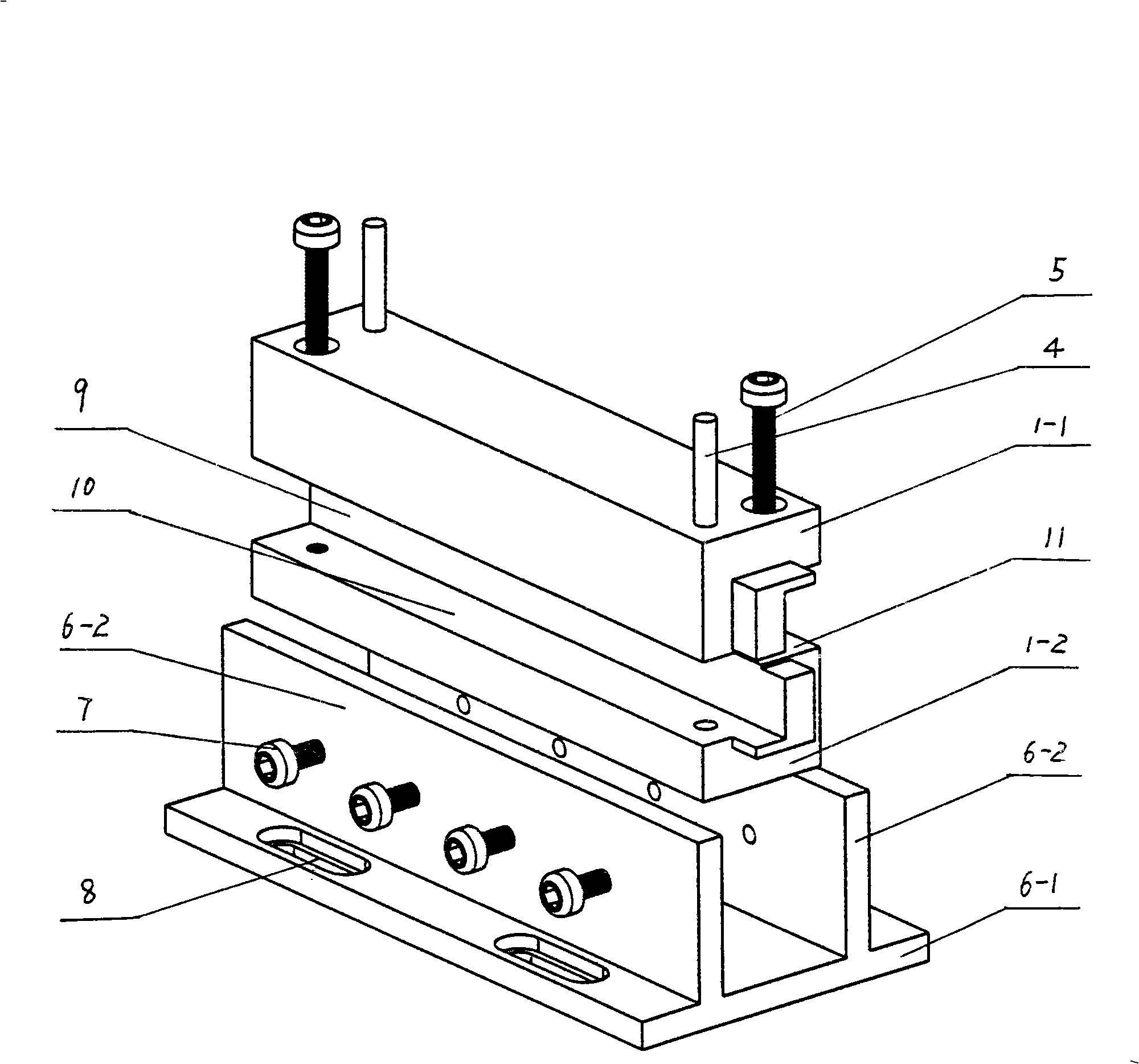
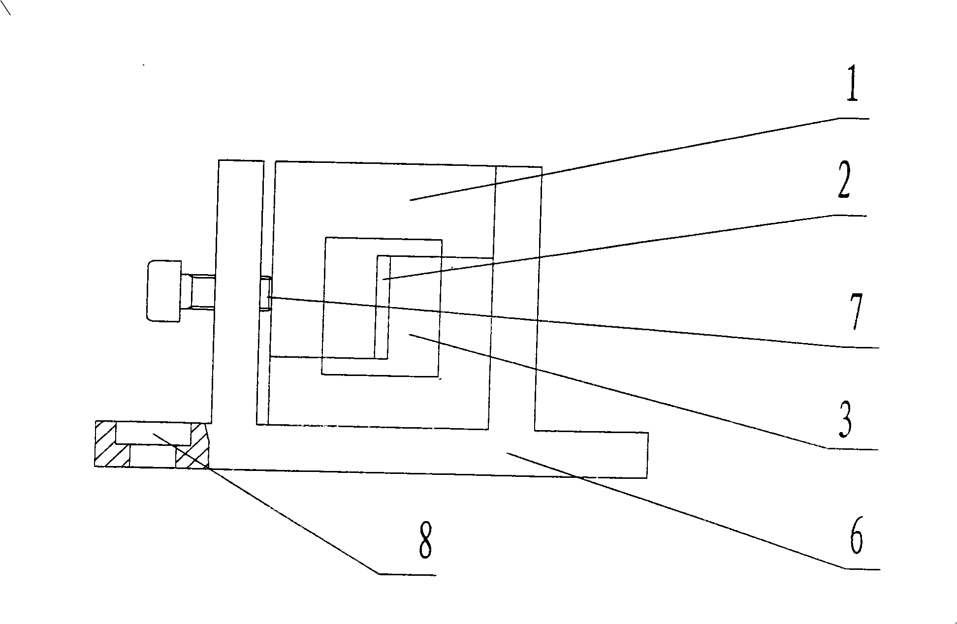
[0028] Embodiment 1: see figure 1 , figure 2 , an X-ray collimator device, comprising a base 6, characterized in that: a fixedly connected slit body 1 is set on the base 6, and a straight slit 2 is set in the slit body 1.

[0029] The above-mentioned slit 2 is a rectangular slit.

[0030] The above-mentioned slit main body 1 is interlacedly fastened by the inner fastening surface 10 and the outer fastening surface 11 of the overall L-shaped upper fastener 1-1 and the lower fastener 1-2 along the direction of the optical path, and is positioned at both ends. The pin 4 and the positioning screw 5 are fixedly formed, and its shape is a cuboid; the slit 2 is between the inner surface 9 of the upper fastener 1-1 and the lower fastener 1-2 and the inner fastening surface 10 gap between.

[0031] The center line of the slit 2 is located at the center of the slit body 1 .

[0032] A boss 3 is provided at one end of the above-mentioned slit main body 1, and the boss 3 is composed ...

Embodiment 2

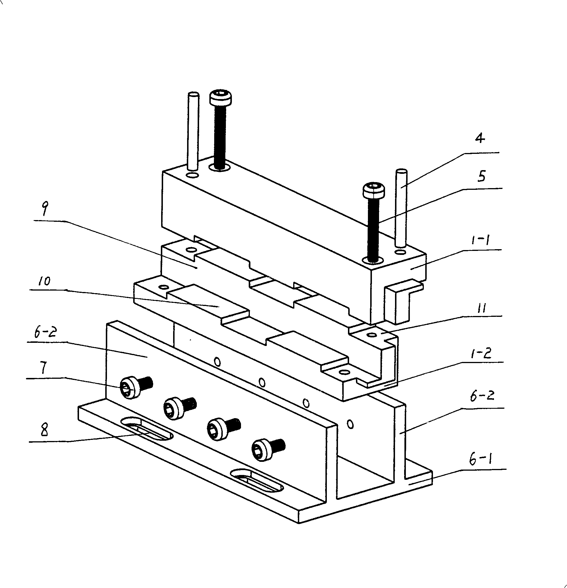
[0034] Example 2: see image 3 , Figure 4The structure difference between this embodiment and embodiment 1 is that: the inner fastening surface 10 and the outer fastening surface 11 of the upper fastener 1-1 and the lower fastener 1-2 are along the The concave-convex stepped surface with mutually matched optical path directions has two concave-convex fastening surfaces.

[0035] Other structures are the same as in Embodiment 1.

Embodiment 3

[0036] Embodiment 3: see Fig. 5, Figure 6 , the structure difference between this embodiment and embodiment 1 is: the slit 2 is a cylindrical circular hole slit; the slit body 1 is composed of an integral rectangular upper fastener 1-1 and a lower fastener 1-2 is buckled along the direction of the light path, and is fixed by positioning pins 4 and positioning screws 5 at both ends, and its shape is a cuboid; the slit 2 is composed of the upper fastener 1-1 and the The lower fastener 1-2 is formed by fastening the corresponding semicircular arc surface on the fastening surface. The fastening surface of the upper fastener 1-1 and the lower fastener 1-2 is a concave-convex stepped surface that cooperates with each other along the optical path direction, the number of the concave-convex fastening surface is one, and the concave-convex stepped surface The height is greater than the radius of the circular hole slit, and an opening is arranged on the convex step surface above the s...


PUM


Abstract

The invention relates to an X-ray collimator device which comprises a base (6). The invention is characterized in that: the base (6) is fixedly connected with a slit body (1); a cut-through slit (2) is arranged in the slit body (1); the slit (2) is rectangular; an internal snap-fitting plane (10) and an outer snap-fitting plane (11) of an L-shaped upper fastener (1-1) and a lower fastener (1-2) are snap-fitted in a staggered way along an optical path direction with a convex step face and a concave step face which are mutually matched, and fixed with a positioning pin (4) and a positioning screw (5) so as to form the slit body (1), the appearance of which is a regular hexahedron. The slit of the invention used for the collimator device of an X-ray test analysis instrument device has accurate positioning and does not produce a penumbra region or X-ray scattering interference; the processing and the use assembly debugging are convenient; the fast replacement is convenient; the precision and the efficiency of the test analysis are reliably enhanced; and the requirement of the high precision test can be met.

Description

technical field [0001] The invention relates to a collimator device for X-ray test and analysis equipment. Background technique [0002] In the existing X-ray test and analysis equipment, the two collimator devices used are respectively fixed at the X light source and the detector. The scattered rays generated by the sample to be tested pass through the slit of another collimator device and enter the detector for corresponding test analysis. The collimator device usually consists of a base, an insert frame and more than one slit insert, the base is fixed on the instrument and equipment by screws, the insert frame is fixedly connected with the base, and the slit insert is inserted on the insert frame The two inserting sides of the slit insert are positioned by springs in the slot of the insert frame; each slit insert has a rectangular slit with a certain width and height in the middle, and several slits on the insert frame The center of the slit of the slit insert is theore...

Claims


Application Information

Patent Timeline
Patent Type & Authority Applications(China)
IPC IPC(8): G21K1/02G01N23/00
Inventor 郑林李迪凡何长光彭正坤
Owner SOUTHWEST TECH & ENG INST
Learn More