

Devices and methods for magnetic enrichment of cells and other particles
A cell and enrichment technology, applied in biochemical equipment and methods, biochemical cleaning devices, enzymology/microbiology devices, etc., can solve problems such as insufficient enrichment of samples and rare components
- Summary
- Abstract
- Description
- Claims
- Application Information
AI Technical Summary
Problems solved by technology
Method used
Image

Examples
Embodiment 1
[0310] Embodiment 1: Silicon device of multi-channel 14 three-segment array duplex
[0311] Figure 42A -42E shows an exemplary device with the following features.
[0312] Dimensions: 90mm×34mm×1mm
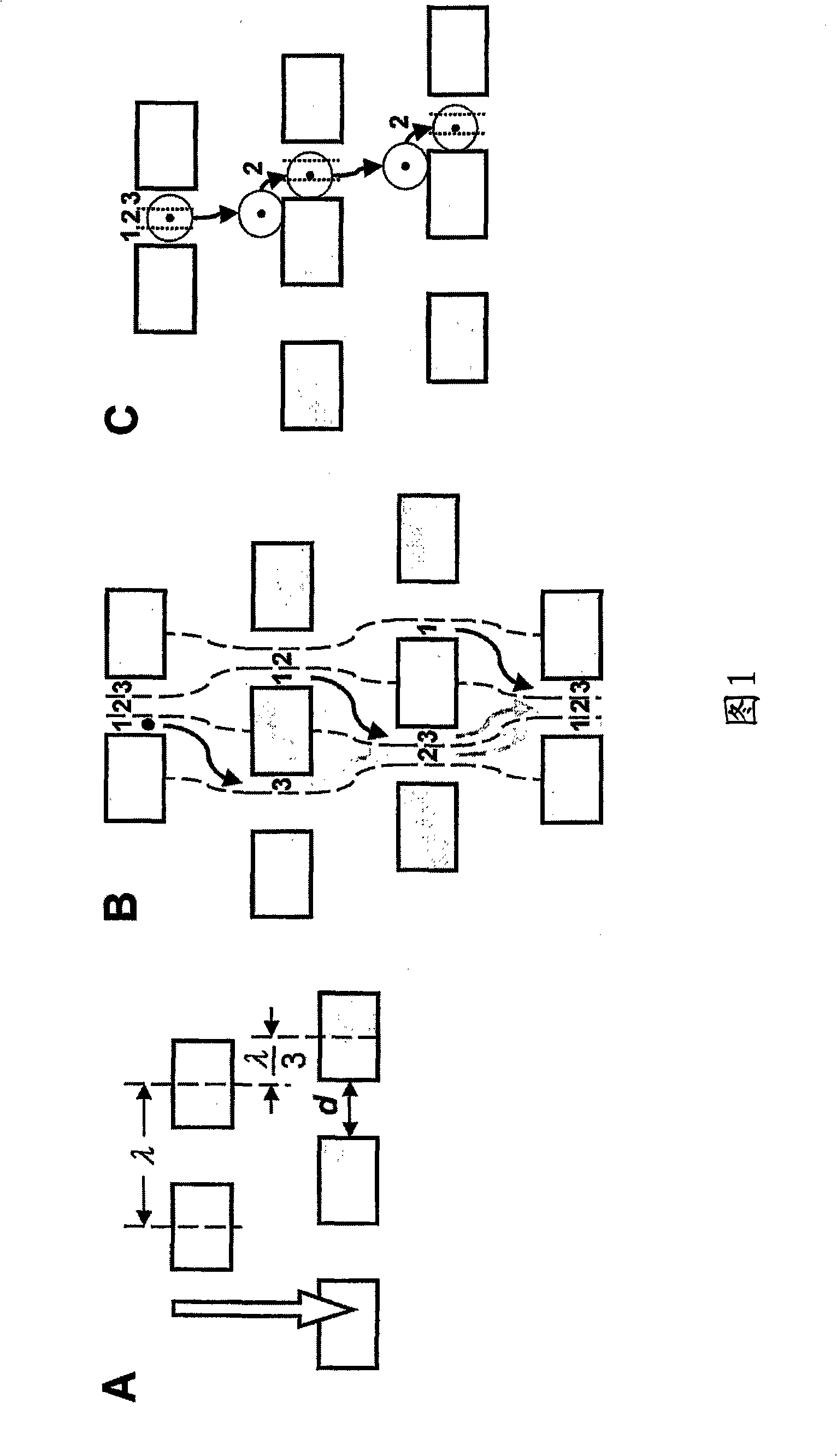
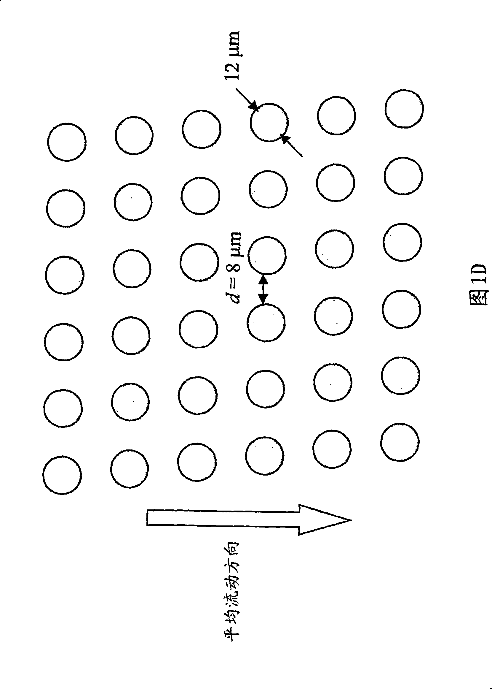
[0313] Array design: three sections, the gap size of the first, second and third sections = 18, 12 and 8 μm, respectively. Bifurcation rate = 1 / 10. Diad, single bypass channel
[0314] Device design: multi-channel 14-array duplex, flow resistance device for flow stability
[0315] Device Assembly: Arrays and channels are assembled in silicon using standard photolithography and deep silicon reactive etch techniques. The etching depth is 150 μm. The via holes for fluid entry were made using KOH wet etching. The silicon substrate was sealed to the etched side using hemocompatible pressure sensitive adhesive (9795, 3M, St Paul, MN) to form an encapsulated fluid channel.
[0316] Device Packaging: The device is joined to a plastic composite tube with an external fluid reservoi...
Embodiment 2
[0323] Embodiment 2 Silicon device of multiplex 14 single-segment array duplexes
[0324] Figures 44A-44D An exemplary device is shown with the following features.
[0325] Dimensions: 90mm×34mm×1mm
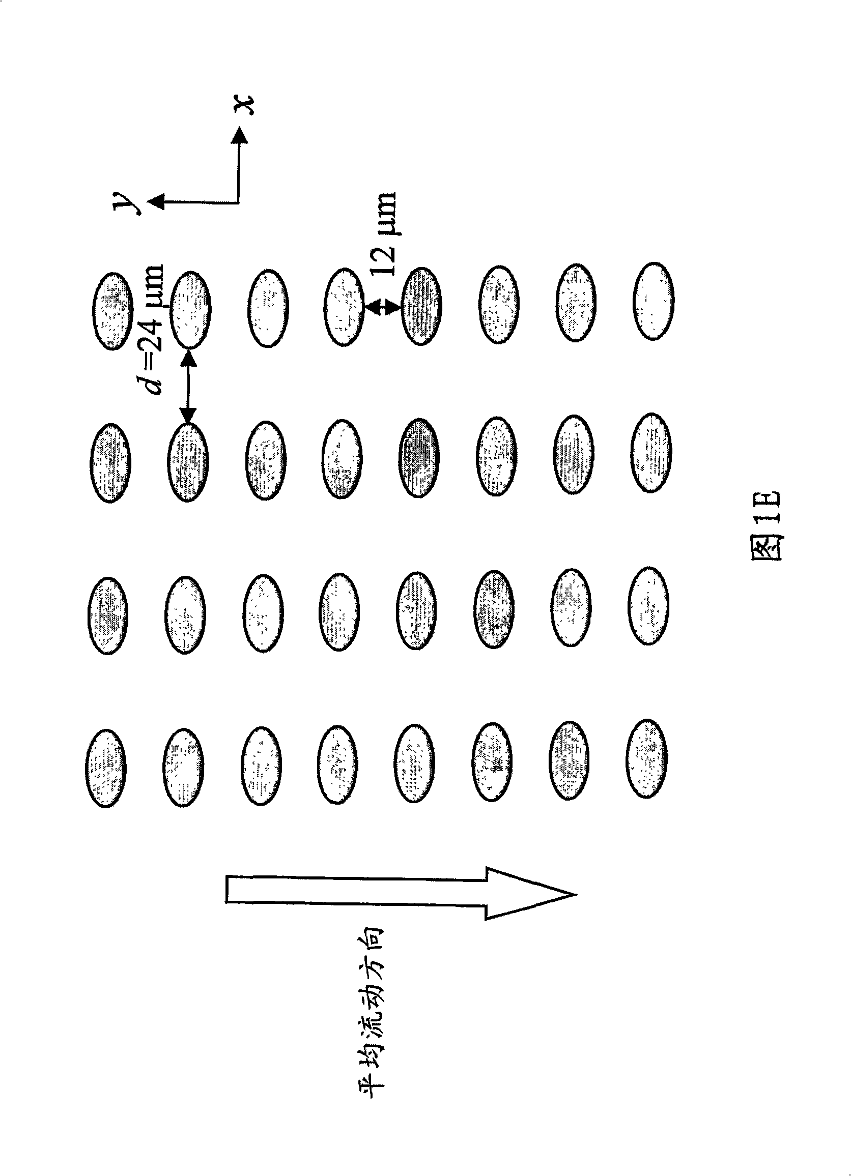
[0326] Array design: 1 segment, gap size = 24 μm. Bifurcation rate = 1 / 60. Diad, dual bypass channels
[0327] Device design: multi-channel 14-array duplex, flow resistance device for flow stability
[0328] Device Assembly: Arrays and channels are assembled in silicon using standard photolithography and deep silicon reactive etch techniques. The etching depth is 150 μm. The via holes for fluid entry were made using KOH wet etching. The silicon substrate was sealed to the etched side using hemocompatible pressure sensitive adhesive (9795, 3M, St Paul, MN) to form an encapsulated fluid channel.
[0329] Device Packaging: The device is joined to a plastic composite tube with an external fluid reservoir that delivers blood and buffer to the device and extracts the resulting...
Embodiment 3
[0334] Example 3: Separation of Fetal Cord Blood
[0335] Figure 45 shows a schematic diagram of an apparatus for separating nucleated cells from fetal cord blood.
[0336] Dimensions: 100mm×28mm×1mm
[0337] Array design: three sections, the gap size of the first, second and third sections = 18, 12 and 8 μm, respectively. Bifurcation rate = 1 / 10. Diad, double bypass channel.
[0338] Device design: multi-channel 10-array duplex, flow resistance device for flow stability.
[0339] Device Assembly: Arrays and channels are assembled in silicon using standard photolithography and deep silicon reactive etch techniques. The etching depth is 140 μm. The via holes for fluid entry were made using KOH wet etching. The silicon substrate was sealed to the etched side using hemocompatible pressure sensitive adhesive (9795, 3M, St Paul, MN) to form an encapsulated fluid channel.
[0340] Device Packaging: The device is joined to a plastic composite tube with an external fluid reserv...
PUM
 Abstract
Description
Claims
Application Information