Ultra-high pressure automatic oiling device

An automatic oil injection and ultra-high pressure technology, which is applied in fluid pressure converters, metal processing, metal processing equipment, etc., can solve the problems of reduced wheel and axle performance indicators, inability to adapt to high-speed trains, unfavorable wheel maintenance, etc., to improve product quality and stability performance, reduced scrap rate, and reduced power requirements

Inactive Publication Date: 2008-11-19
CHANGCHUN EQUIP TECH RES INST
0 Cites 1 Cited by

AI-Extracted Technical Summary

Problems solved by technology

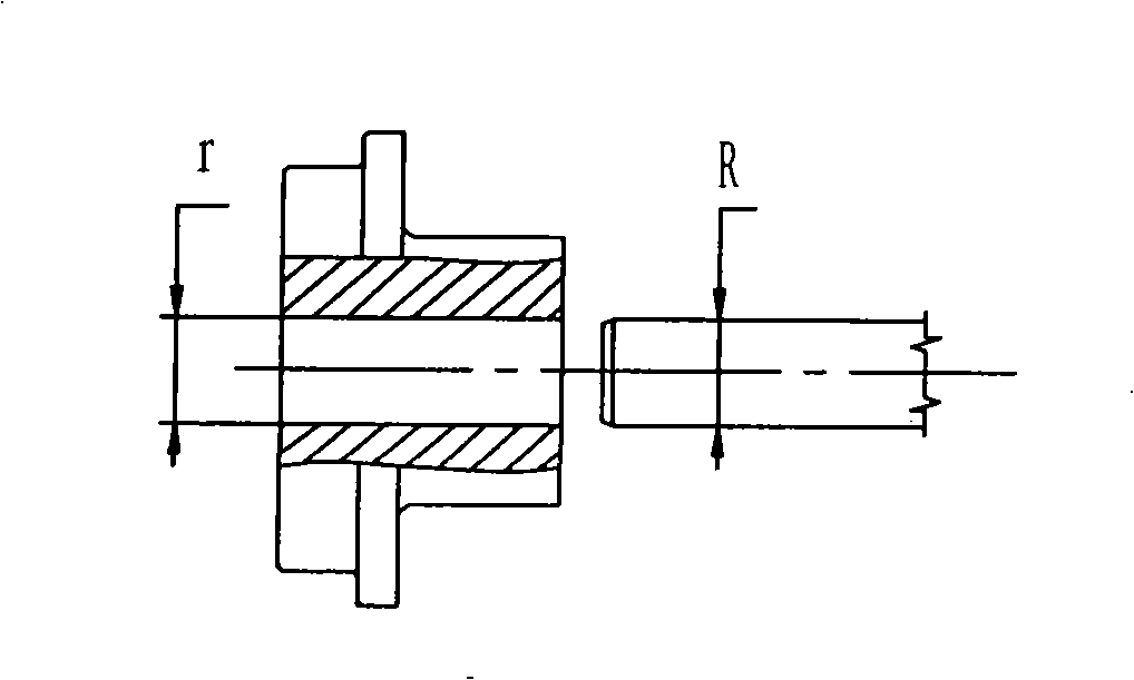
[0006] 1. Due to the interference during the press-fitting process, the surface of the wheel and the shaft will be worn to a certain extent, thereby reducing the performance index of the wheel shaft
[0007] 2. Due to the damage during the press-fitting process, there is a certain limit to the rotation speed of the wheel, which cannot meet the needs of high-speed trains
[0008] 3. There are strict requirements on the interference size and ...

Abstract

The invention provides a super high pressure automatic oiling device, which relates to the improvement in manufacture and maintenance technologies on a rail-mounted vehicle. The device is characterized in that: a hydraulic oil way together with a gear pump and a solenoid relief valve forms a first hydraulic system; an oil way outlet of the first hydraulic system is connected with a booster through a solenoid reversal valve to form a second hydraulic system; a direction increaser outlet is communicated with an oil outlet. The device has the advantages that: firstly, the adoption of an oiling press mounting wheel shaft overcomes shortcomings and defects of press mounting of the prior wheel shaft; secondly, the technology solves one of major process production technologies for Chinese production of high speed vehicles; thirdly, rejection rate is reduced, so production cost can be saved; work efficiency is increased and also products quality and stability can be improved; finally, the technology can be applied not only to railway locomotives but also to products production of other industries, and has extensive applications, market prospects and popularization values.

Application Domain

Fluid-pressure convertersMetal working apparatus

Technology Topic

Gear pumpRelief valve +4

Image

  • Ultra-high pressure automatic oiling device
  • Ultra-high pressure automatic oiling device
  • Ultra-high pressure automatic oiling device

Examples

  • Experimental program(1)

Example Embodiment

[0025] Examples:
[0026] The present invention will be further described with reference to the drawings:
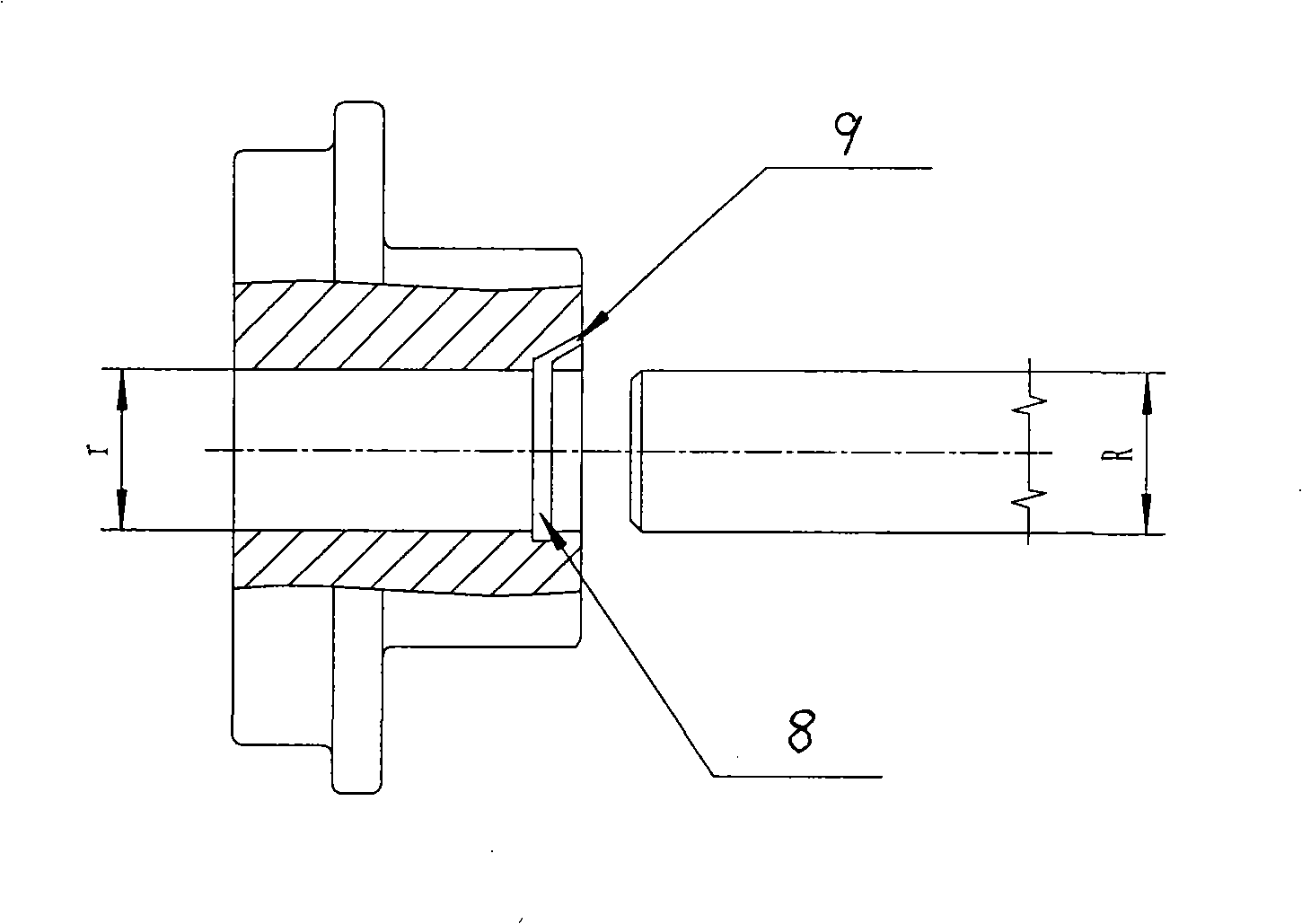
[0027] As shown in Figure 2, 8 is an oil injection groove, and 9 is an oil injection hole; first, an oil injection groove is opened on the edge of the hub, and an oil injection hole is drilled. During the press-fitting process, ultra-high pressure hydraulic oil is injected to expand the hub and expand the hub. The joint surface of the shaft produces a layer of oil film, which is pressed into the rear wheel and the shaft is not worn. After unloading, the wheel hub is restored to realize wear-free press fitting. The same applies when the wheel is retracted.
[0028] The working principle is shown in Figure 3:
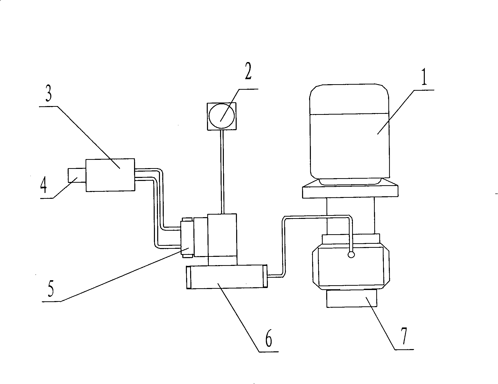
[0029] 1 is an electric motor, 2 is a return oil filter, 3 is a supercharger, 4 is an oil outlet, 5 is an electromagnetic directional valve, 6 is an electromagnetic relief valve, and 7 is a gear pump.
[0030] The operation of the motor drives the gear pump to rotate to generate pressure oil. When the device is empty, the electromagnetic overflow valve is in the unloading state, and the pressure oil flows directly back to the oil tank to form a primary hydraulic system. When the device needs to be filled with oil, the electromagnetic overflow valve changes direction The pressure oil is switched by the electromagnetic reversing valve to supply oil to the supercharger or unload the supercharger to form a secondary hydraulic system. The direction increaser outputs ultra-high pressure oil to the working point through the oil outlet.
[0031] The working principle of hydraulic pressure is shown in Figure 4:
[0032] 11 is the liquid level and liquid temperature gauge, 12 is the air filter, 13 is the oil filter, 14 is the gear pump, 15 is the motor, 16 is the oil return filter, 17 is the one-way valve A, 18 is the electromagnetic overflow valve , 19 is a pressure gauge, 20 is an electromagnetic reversing valve, 21 is a pressure comparator, 22 is a one-way valve B, 23 is a one-way proportional valve, 24 is a one-way valve C, and 25 is a pressure gauge.
[0033] The working principle of hydraulic pressure is as follows:
[0034] 1. Connect the motor to drive the gear to run, so that the hydraulic oil generates a certain pressure, the pressure range is 0-15MPa.
[0035] 2. When the device is empty, the electromagnetic overflow valve is in the unloading state, that is, the hydraulic oil flows directly back to the tank. When it needs to work, the 1DT electromagnet is used to change the direction to make the system generate 0~15MPa pressure, and the pressure gauge can display the system pressure.
[0036] 3. Turn on the 2DT of the electromagnetic reversing valve and compare the hydraulic oil of 0~15MPa through the pressure comparator. If it is less than the pressure set by the system, pressurize it through the one-way proportional valve until the pressure reaches the set range. The pressure range of hydraulic oil is 0~200MPa.
[0037] 4. The hydraulic oil of 0~200MPa is pressurized twice and sent to the working point through the oil outlet H and the pressure gauge shows the high pressure oil pressure.
[0038] 5. After the work is completed, the system pressure is unloaded through (10) 3DT of electromagnetic directional valve, and returned to the fuel tank through (6) refueling filter
[0039] The electrical control principle is shown in Figure 5:
[0040] 1. The electrical control adopts Siemens programmable controller PLC control, through the position sensor grating ruler, the displacement and position control of the pressed equipment. Set the press-fitting pressure through the pressure sensor.
[0041] 2. The control can adopt automatic control and manual control.
[0042] Automatic control: Input the control data into the controller before processing, the controller can detect the displacement according to the data, and the position will automatically fill or unload the oil.
[0043] Manual control: according to the processing conditions, artificial oil injection or unloading.

PUM

no PUM

Description & Claims & Application Information

We can also present the details of the Description, Claims and Application information to help users get a comprehensive understanding of the technical details of the patent, such as background art, summary of invention, brief description of drawings, description of embodiments, and other original content. On the other hand, users can also determine the specific scope of protection of the technology through the list of claims; as well as understand the changes in the life cycle of the technology with the presentation of the patent timeline. Login to view more.

Similar technology patents

Dewatering and drainage construction process for inclined shaft of extra-long water-rich karst tunnel

PendingCN113482713AImprove drainage efficiencyReduced Power Requirements
Owner:中建七局第一建筑有限公司

Central sensor restoration method and central sensor

ActiveCN105632955AReduced Power RequirementsReduce use cost
Owner:WUXI CHINA RESOURCE MICRO ASSEMBLY TECH

Method and apparatus for mixing

InactiveCN1138586CReduced Power Requirements
Owner:COMMONWEALTH SCI & IND RES ORG +1

Radio frequency amplifier with reduced intermodulation distortion

InactiveCN1193498CReduced Power RequirementsEasy to implement
Owner:MURATA MFG CO LTD

Stirring paddle for reaction kettle

InactiveCN110961058Areduce weightReduced Power Requirements
Owner:泰兴市宏伟机电环保科技有限公司

Classification and recommendation of technical efficacy words

  • Reduced Power Requirements
  • Reduce scrap rate

By-pass switch trigger device of MMC flexible direct-current electronic module

ActiveCN104009613AReduced Power Requirementsreduce volume
Owner:XJ ELECTRIC

Contact type strip suction moving machine

InactiveCN105947667AImprove Adaptability and Work EfficiencyReduced Power Requirements
Owner:DAYA JIANGSU FLOOR

Energy-saving yarn dyeing system for dyeing

InactiveCN105821603AReduced Power Requirementslow cost
Owner:NANTONG DONGGENG MACHINERY CO LTD

Artificial limb arm joint with multiple freedom degrees

ActiveCN109464227AReduced Power Requirementscompact internal structure
Owner:SHENZHEN INST OF ADVANCED TECH CHINESE ACAD OF SCI
Why Eureka
Try Eureka