Filtrating type vapor-liquid separating device

A vapor-liquid separation and filtration technology, applied in separation methods, charging systems, and liquid degassing, etc., can solve the problems of fuel injector safety hazards, inhaled gas, and impact on working stability, to protect normal work and prolong The effect of service life

Inactive Publication Date: 2008-11-26
塞尔福(厦门)工业有限公司
View PDF4 Cites 8 Cited by
  • Summary
  • Abstract
  • Description
  • Claims
  • Application Information

AI Technical Summary

Problems solved by technology

This kind of vapor-liquid separation device is located under the fuel tank and has a large size, while the air bubble removal device is located in the belly of the fuel tank. The pipeline connecting the two is slender and located outside the fuel tank, which is not good in aesthetics, productivity and reliability. Ideal
At the same time, the height difference of this type of vapor-liquid separation device relative to the fuel injector is small, and a slight air bubble may cause the fuel supply flow and pressure to be too small, causing the fuel injector to inhale gas, and the working stability will be affected.
In addition, due to structural limitations, this type of vapor-liquid separation device cannot be installed with a fuel filter that has a good filtering effect and does not affect the fuel supply system, which poses a great safety hazard to the fuel injector.

Method used


Image

  • Filtrating type vapor-liquid separating device
  • Filtrating type vapor-liquid separating device
  • Filtrating type vapor-liquid separating device

Examples


Embodiment 1

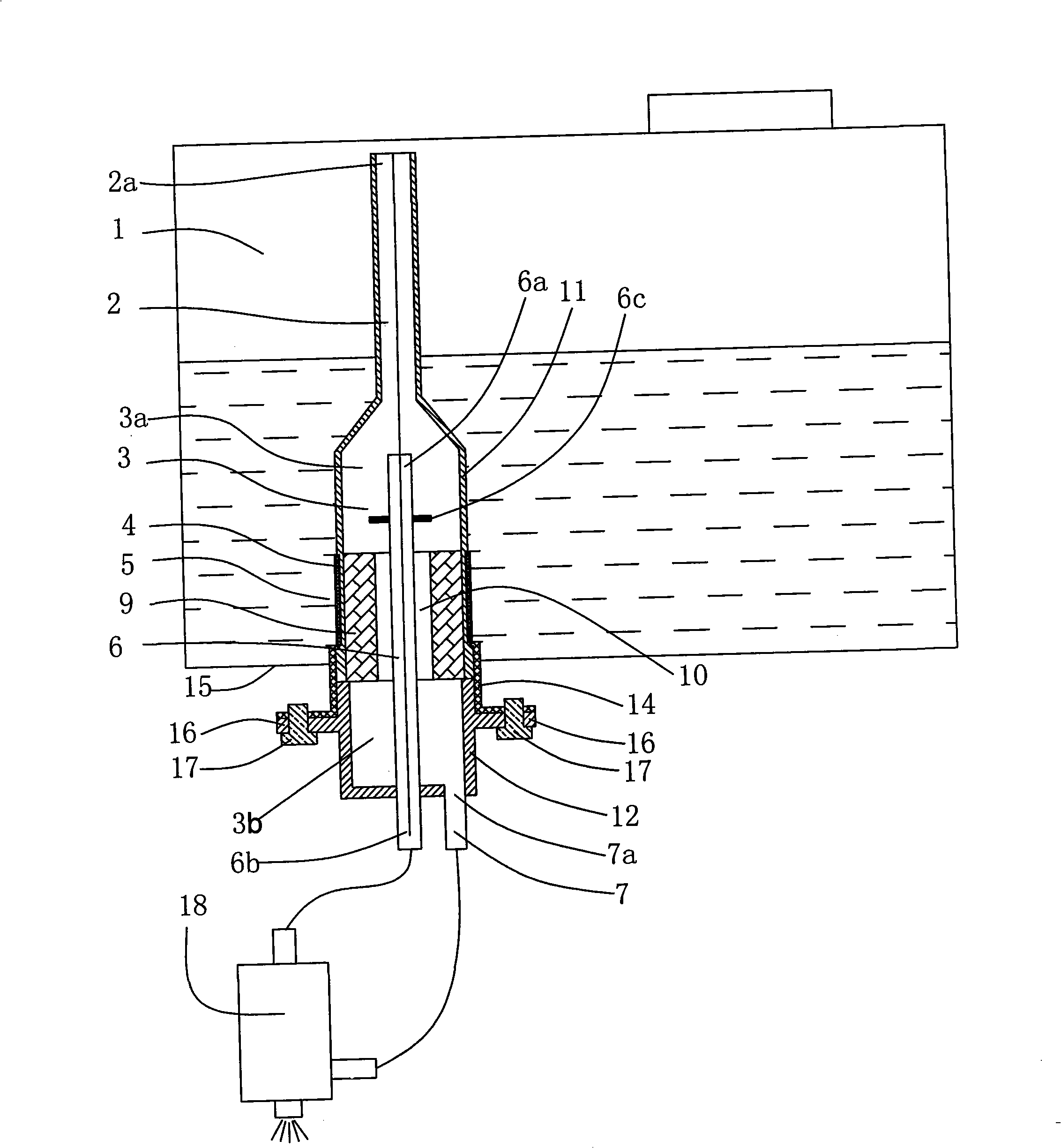
[0033] figure 1It is an embodiment of the filter type vapor-liquid separation device of the present invention. As shown in the figure, the device has a first fuel filter 4 and a second fuel filter 9 placed inside the fuel tank, and the fuel outlet pipe 7. An oil return pipe 6, an oil inlet 5 and an exchange volume composed of the upper body 11 and the lower body 12. 3. The upper body 11 and the lower body 12 are pressed against each other through the thread 13, and the second filter 9 is fixed at the same time In the exchange volume 3.

[0034] The first fuel filter 4 is made of mesh material, located on the periphery of the exchange volume 3 , and the mesh gap is formed as an oil inlet 5 .

[0035] The columnar hollow second fuel filter 9 divides the exchange volume 3 into an upper volume 3 a and a lower volume 3 b, wherein the cavity forms an intermediate oil passage 10 . The oil return pipe 6 passes through the lower volume 3b and leads to the upper volume 3a through the ...

Embodiment 2

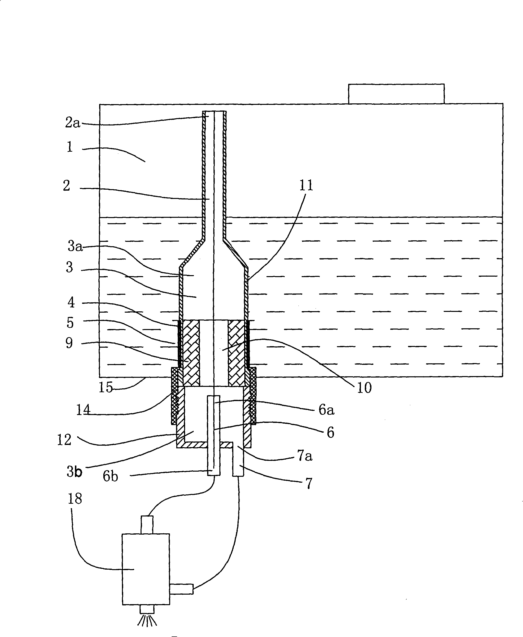
[0042] figure 2 It is another embodiment of the filter type gas-liquid separation device of the present invention, as shown in the figure, the difference from Embodiment 1 is that firstly the oil return pipe 6 does not pass through the middle oil passage 10 to reach the upper volume 3a , and only reach the position where the lower volume 3b is close to the middle oil passage 10; secondly, the lower body 12 has no protruding outer edge, and the upper body 11 and the second A fuel filter 9 is fixed in the exchange volume 3 . The oil return of the fuel injector 18 directly enters the lower volume 3b from the oil return pipe 6, the liquid fuel discharged from the oil return pipe 6 directly enters the oil outlet pipe 7 downwards, and participates in the circulation flow again, and the air bubbles discharged from the oil return pipe 6 are discharged from the middle oil passage 10 Enter the upper volume 3a, and finally enter the fuel tank 1 through the exhaust passage 2.

Embodiment 3

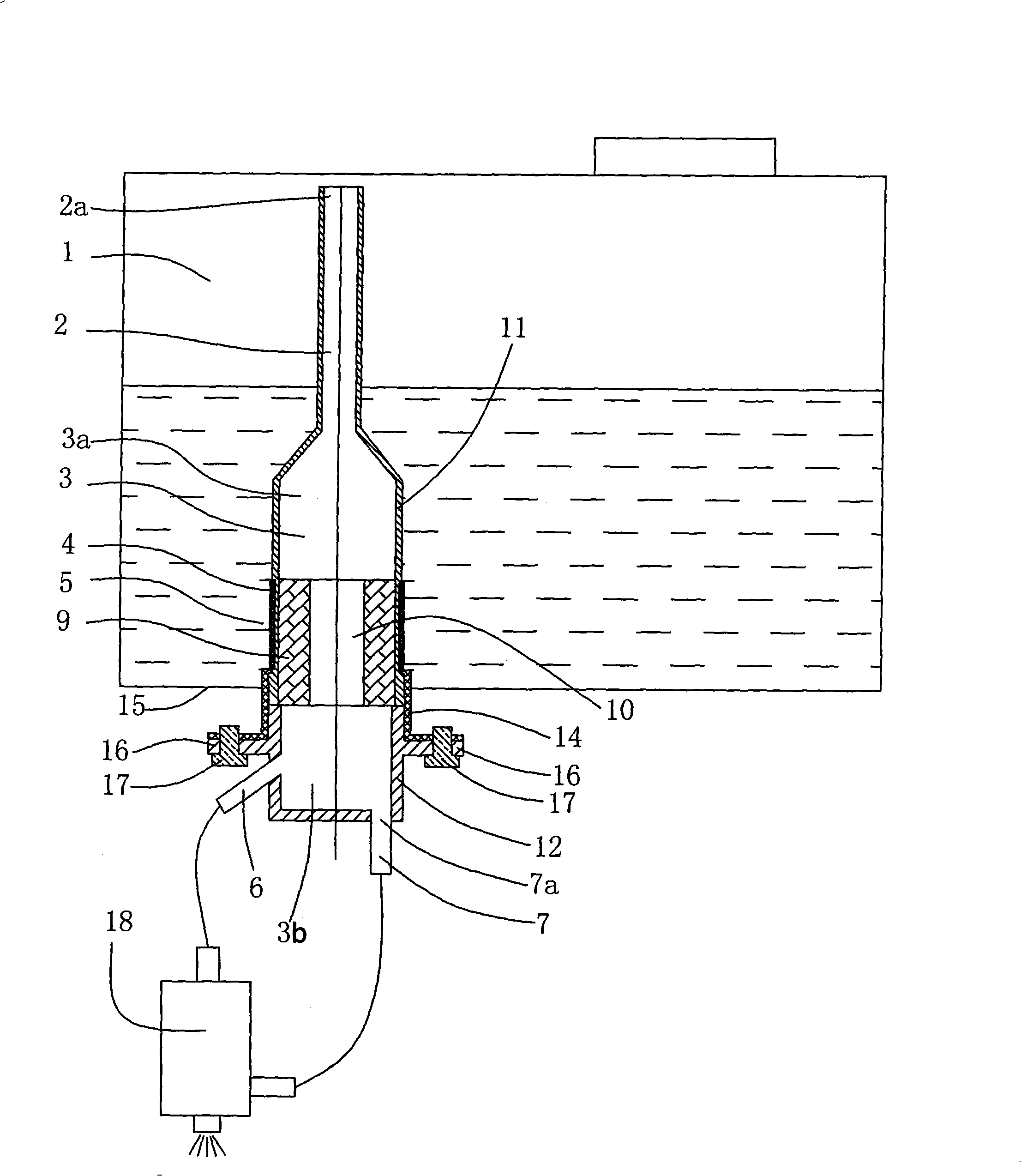
[0044] image 3 Another implementation example of the filter-type gas-liquid separation device of the present invention, as shown in the figure, differs from Embodiment 1 in that: the oil return pipe 6 is an oil return nozzle extending outward on the lower body 12, and its The axis and the axis of the oil outlet pipe 7 may form a certain angle. The oil return of the fuel injector 18 directly enters the lower volume 3b from the oil return pipe 6, the liquid fuel discharged from the oil return pipe 6 directly enters the oil outlet pipe 7 downwards, and participates in the circulation flow again, and the air bubbles discharged from the oil return pipe 6 are discharged from the middle oil passage 10 Enter the upper volume 3a, and finally enter the fuel tank 1 through the exhaust passage 2.


PUM


Abstract

A filtering gas-liquid separation device belongs to the technical field of fuel supply of an engine which includes an exchange cubage and an oil return tube used for receiving the return oil of the fuel sprayer; an exhaust channel is arranged above the exchange cubage; an oil outlet tube used for supplying oil to a fuel sprayer is arranged below the exchange cubage; an oil inlet used for leading the fuel to enter the device from an oil box is arranged in a fuel box; a multiple fuel filters are arranged between the oil inlet and the exchange cubage; the outlet of the oil return tube is arranged in the exchange cubage so as to lead the distance to be larger than the size of the largest confusion area of the liquid of the oil return tube and lead the air bladders of the oil return tube to be incapable of entering the oil outlet tube. The invention can be suitable for a pulse electric fuel spraying system which not only ensures the fuel steams to be exhausted in time, increase the filtering of multiple fuels and lead the fuel spraying system to work reliably, but also can carry out complete protection on the fuel sprayer and obtain further improvements on the productive performance and beautiful performance simultaneously.

Description

technical field [0001] The invention belongs to the technical field of engine (internal combustion engine) fuel supply, and in particular relates to a vapor-liquid separation device suitable for a pulse type electronic fuel injection device with a low-pressure fuel supply circuit. Background technique [0002] In a pulsed electronic fuel injection system that has been widely used (such as Chinese patent ZL01103954.X, and Japanese patent 2003-83192), the fuel is directly obtained from the fuel tank under normal pressure. Since commercial gasoline contains low-boiling components, These components will produce a large number of air bubbles under normal pressure or slightly high temperature. If these air bubbles cannot be discharged in time in the fuel supply system, the electronic fuel injection system will appear in an abnormal working state. In addition, gasoline contains more impurities, and the rust in the fuel tank after long-term use also gradually increases. Once these i...

Claims


Application Information

Patent Timeline
Patent Type & Authority Applications(China)
IPC IPC(8): F02M37/00F02M37/22B01D19/00
Inventor 郗大光刘晓吉张平杨延相
Owner 塞尔福(厦门)工业有限公司
Why Eureka
Try Eureka