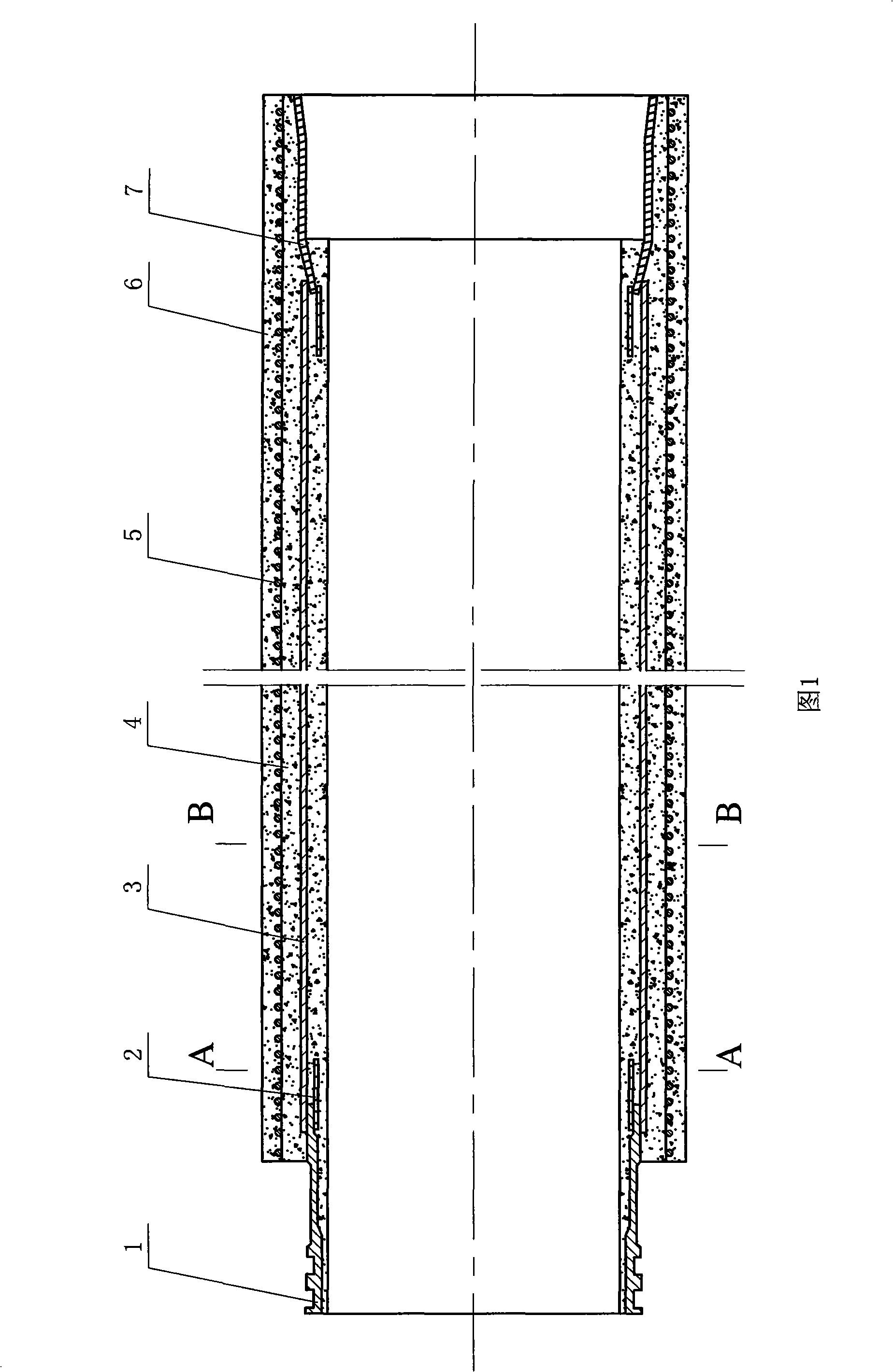
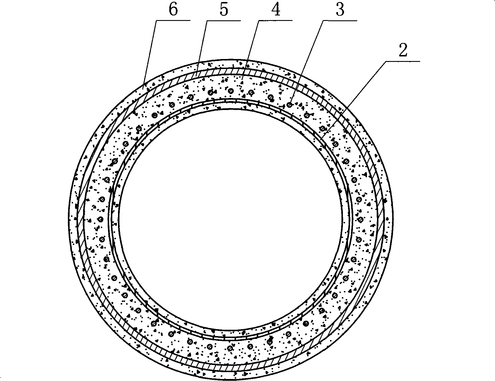
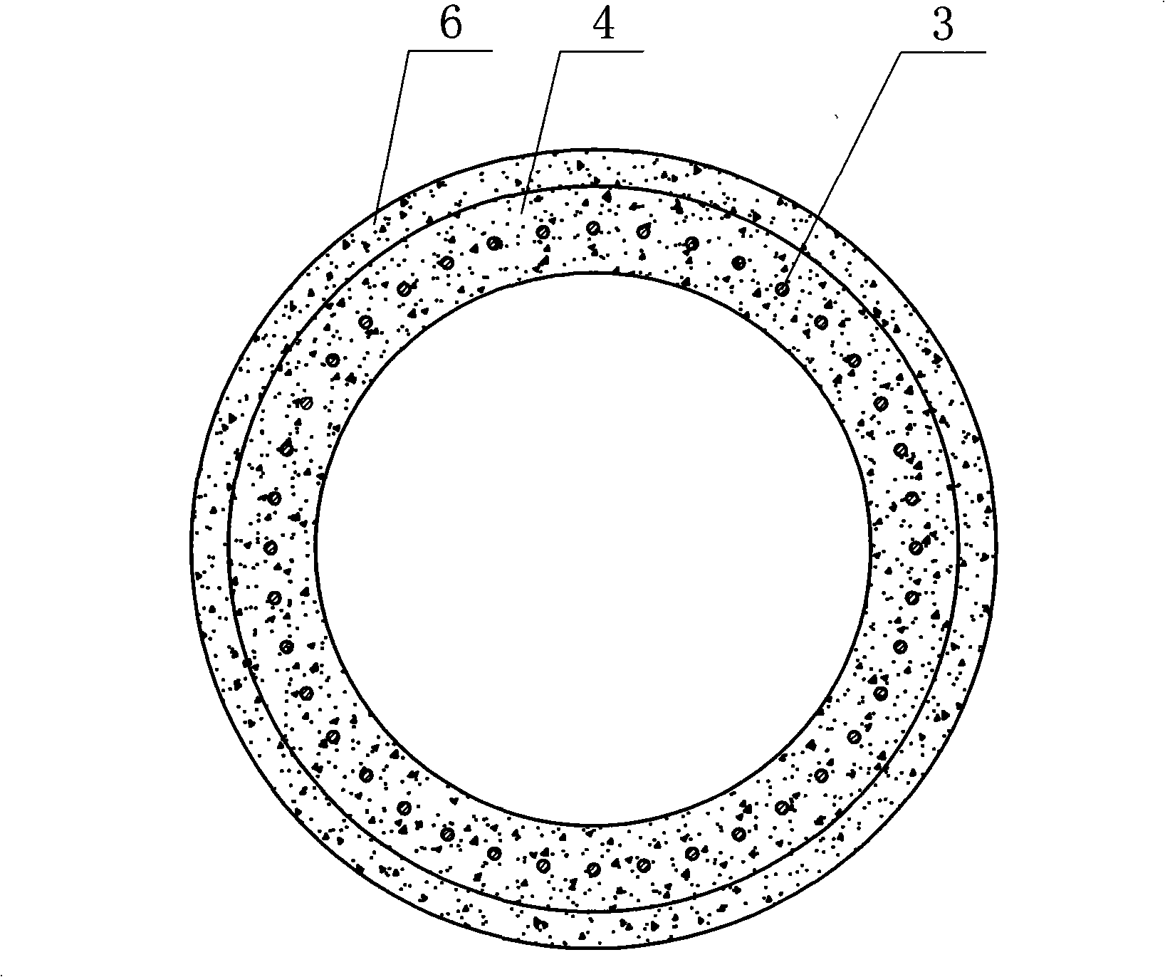
Steel cylinder strengthened steel faucet longitudinal reinforced concrete ceiling coil
A technology of longitudinally reinforced concrete and concrete pipes, which is applied in the direction of sleeve/socket connection, pipes, rigid pipes, etc., can solve the problem of increasing the transportation cost and construction cost of concrete pipe jacking, the limited external pressure load of the pipe body and the limited internal water pressure. Increase the comprehensive cost of concrete pipe jacking construction to achieve the effect of strong resistance to uneven settlement, good water closure of joints, and saving production time
Inactive Publication Date: 2008-11-26
天津万联管道技术开发有限公司
View PDF0 Cites 2 Cited by
- Summary
- Abstract
- Description
- Claims
- Application Information
AI Technical Summary
Problems solved by technology
Concrete jacking pipes are generally used as non-pressure pipes when they are used as drainage pipes. During the construction and installation process such as deviation correction, the concrete jacking pipe is easy to cause damage to the concrete at the nozzle of the concrete jacking pipe, thereby affecting the sealing performance of the joint; especially when the pressure pipeline is installed During the jacking construction, because the pressure pipe cannot be directly jacked, it is necessary to use a concrete jacking pipe with a large enough diameter as a casing for jacking first, and then install the pressure pipeline in the casing, thereby increasing the concrete jacking pipe. Comprehensive construction cost
The tube core of the existing concrete jacking pipe is fixed with two layers of coaxial steel reinforcement skeleton, resulting in a thicker tube core. The main reason is that the concrete tube needs to bear the high external pressure load caused by the construction and the transmission medium high internal pressure load
The concrete jacking pipe of this structure is heavy in weight, the cost of raw materials is high, and the production time is long. It requires high-tonnage hoisting and lifting equipment for installation, which greatly increases the transportation cost and construction cost of concrete pipe jacking.
In addition, the water-tightness of the existing concrete pipe jacking pipeline is not ideal
At present, concrete pipe jacking is mainly used in the field of drainage. The main reasons are: 1. The pipe body bears external pressure load and internal water pressure is limited; 2. The impermeability of the pipe wall is not high; 3. The water-tightness of the socket connection is poor, The above reasons have affected the application of concrete pipe jacking in the field of water supply
Method used
View moreImage
Smart ImageViewing Examples
Examples
Embodiment 1
Login to View More PUM
 Abstract
The invention relates to a steel barrel reinforced steel bell and spigot pre-stressed longitudinal bar concrete push pipe, which consists of a pipe socket, a spigot, a reinforcement cage and a concrete pipe core, wherein, the pipe socket and the spigot are respectively and fixedly arranged at the two ends of the concrete pipe core and the reinforcement cage is coaxially embedded in the concrete pipe core. The reinforcement cage is the longitudinal bar and the steel barrel is respectively, coaxially and fixedly arranged on the pipe socket and the spigot in the concrete pipe core the outer wall of which is poured with a protective layer and the outer wall of the concrete pipe core in the protective layer is twined by a pre-stressed steel wire. The concrete push pipe is simple in the whole structure and scientific and rational in design and has good durability, impermeability and joint water closeness, and besides, the pipe wall is thin and the engineering cost is low, greatly reducing construction cost and transportation cost, so the concrete push pipe is a steel bell and spigot pre-stressed longitudinal bar concrete push pipe with a reinforced steel barrel and higher innovation.
Description
Steel cylinder reinforced steel socket socket prestressed longitudinal reinforced concrete pipe jacking technical field The invention relates to concrete pipes, in particular to a prestressed longitudinal reinforced concrete jacking pipe with a steel cylinder reinforced steel socket. Background technique Pipe jacking is generally used in areas where it is difficult to open grooves, has high construction environment requirements, and does not cause ground subsidence under specific geographical conditions, such as underground construction under railways and highways. Concrete jacking pipes are generally used as non-pressure pipes when they are used as drainage pipes. During the construction and installation process such as deviation correction, the concrete jacking pipe is easy to cause damage to the concrete at the nozzle of the concrete jacking pipe, thereby affecting the sealing performance of the joint; especially when the pressure pipeline is installed During the jackin...
Claims
Login to View More Application Information
Patent Timeline
 Patent Type & Authority Applications(China)
IPC IPC(8): F16L9/153F16L21/00
Inventor 赵斌张亮
Owner 天津万联管道技术开发有限公司
Features
- R&D
- Intellectual Property
- Life Sciences
- Materials
- Tech Scout
- Unparalleled Data Quality
- Higher Quality Content
- 60% Fewer Hallucinations
Learn More Browse by: Latest US Patents, China's latest patents, Technical Efficacy Thesaurus, Application Domain, Technology Topic, Popular Technical Reports.
© 2025 PatSnap. All rights reserved.Legal|Privacy policy|Modern Slavery Act Transparency Statement|Sitemap|About US| Contact US: help@patsnap.com


