Display device

A display device and signal technology, applied in the direction of digital output to display equipment, static indicators, optics, etc., can solve problems such as impossible connection, FPC substrate connection, difficult TFT substrate, etc., and achieve the effect of suppressing manufacturing costs

Inactive Publication Date: 2008-11-26
SHARP KK
View PDF1 Cites 5 Cited by
  • Summary
  • Abstract
  • Description
  • Claims
  • Application Information

AI Technical Summary

Problems solved by technology

Therefore, since the number of terminals necessary for video signal input is slightly less than 40 pins, it is difficult to connect the TFT substrate to the FPC substrate, and it is also considered that it is impossible to connect when the wiring is detoured in some cases.

Method used


Image

  • Display device
  • Display device
  • Display device

Examples


Embodiment Construction

[0195] Hereinafter, first and second embodiments and modifications thereof of the present invention will be described with reference to the drawings.

[0196]

[0197]

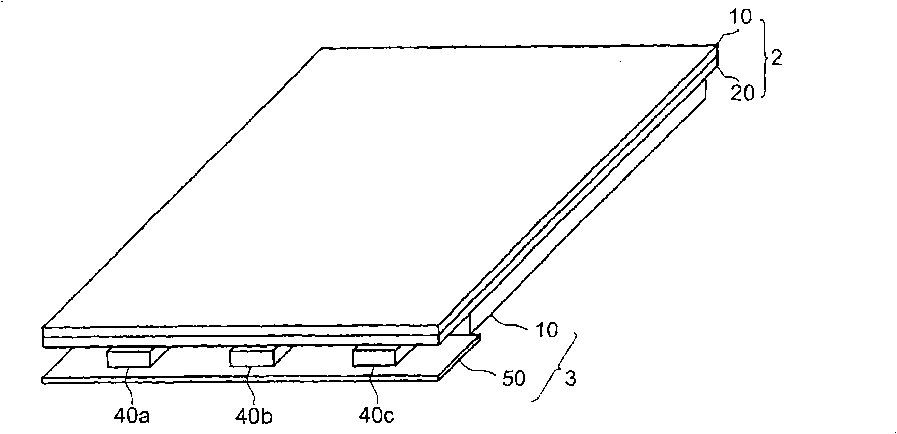
[0198]FIG. 1 is a perspective view illustrating a partial structure of a liquid crystal display device according to a first embodiment of the present invention. This liquid crystal display device is a transmissive type (or semi-transmissive type) liquid crystal display device. Although it has almost the same structure as the conventional one, it is different from the conventional structure in that there is no FPC board for video signal transmission, but a new signal transmission board. The light-receiving element and receiving circuit described later.

[0199] As shown in FIG. 1 , this liquid crystal display device has: a liquid crystal panel (liquid crystal display unit) 2 including a conventional CF substrate 10 and a different TFT substrate 20 on which a light receiving element and a receiving circuit a...


PUM


Abstract

A display device provided with a signal transmitting mechanism, which has reduced number of pins of an FPC substrate to be connected with a TFT substrate or eliminates such pins and is easily applicable even to a small device. The display device is provided with a light receiving element (90) formed on the TFT substrate of a liquid crystal panel (2), a receiving circuit (100), a display control circuit (200), a video signal line drive circuit (300), a scanning signal line drive circuit (400), a display section (500), and white LEDs (40a-40c) and a LED drive circuit (51) included in a backlight section (3). The LED drive circuit (51) drives a white LED (40) which emits light by an optical (modulation) signal (LS) corresponding to a video signal (VS) given from the external of the device. The receiving circuit (100) generates (demodulates) the video signal (VS) from the signal received through the light receiving element (90).

Description

technical field [0001] The present invention relates to a display device, and more specifically, to a display device using an optical communication method inside the device. Background technique [0002] Conventionally, as a general display device, an active matrix liquid crystal display device including a TFT (Thin Film Transistor: thin film transistor) as a switching element is known. This liquid crystal display device has a liquid crystal panel composed of two insulating substrates (typically glass substrates) facing each other. On one substrate of the liquid crystal panel (hereinafter referred to as "TFT substrate"), scanning signal lines (gate bus lines) and video signal lines (source bus lines) are arranged in a grid pattern, and at the intersections of scanning signal lines and video signal lines A TFT is set nearby. The TFT has a gate electrode connected to a scanning signal line, a source electrode connected to a video signal line, and a drain electrode. The drai...

Claims


Application Information

Patent Timeline
Patent Type & Authority Applications(China)
IPC IPC(8): G09G3/36G02F1/133G02F1/13357G09G3/20G09G3/34G02F1/1335
CPCG09G2360/145G02F1/13452G09G3/3406G09G2370/04G02F2001/133612G09G2320/0626G06F3/14G09G3/2096G09G2370/08G02F1/133612G09G3/36G09G3/20G02F1/133G02F1/1335
Inventor 宫田和彦M·J·布朗洛H·G·沃尔顿
Owner SHARP KK
Why Eureka
Try Eureka