Contact stiffness testing device

A testing device and contact stiffness technology, applied in measurement devices, strength characteristics, instruments, etc., can solve the problems of changing the contact state of the contact surface, reducing the vibration reduction effect of the dry friction damping structure, and increasing the difficulty of changing the contact state of the contact surface. Easy disassembly and replacement, the effect of increasing the loading range

Inactive Publication Date: 2008-12-03
BEIHANG UNIV
View PDF0 Cites 11 Cited by
  • Summary
  • Abstract
  • Description
  • Claims
  • Application Information

AI Technical Summary

Problems solved by technology

In the actual work of the blade with dry friction damping structure, if the tangential contact stiffness of the contact surface is too large, it will increase the difficulty of contact state transition of the contact surface, thereby reducing the vibration reduction effect of the dry friction damping str

Method used


Image

  • Contact stiffness testing device
  • Contact stiffness testing device
  • Contact stiffness testing device

Examples


Embodiment Construction

[0021] The present invention will be further described in detail below in conjunction with the accompanying drawings.

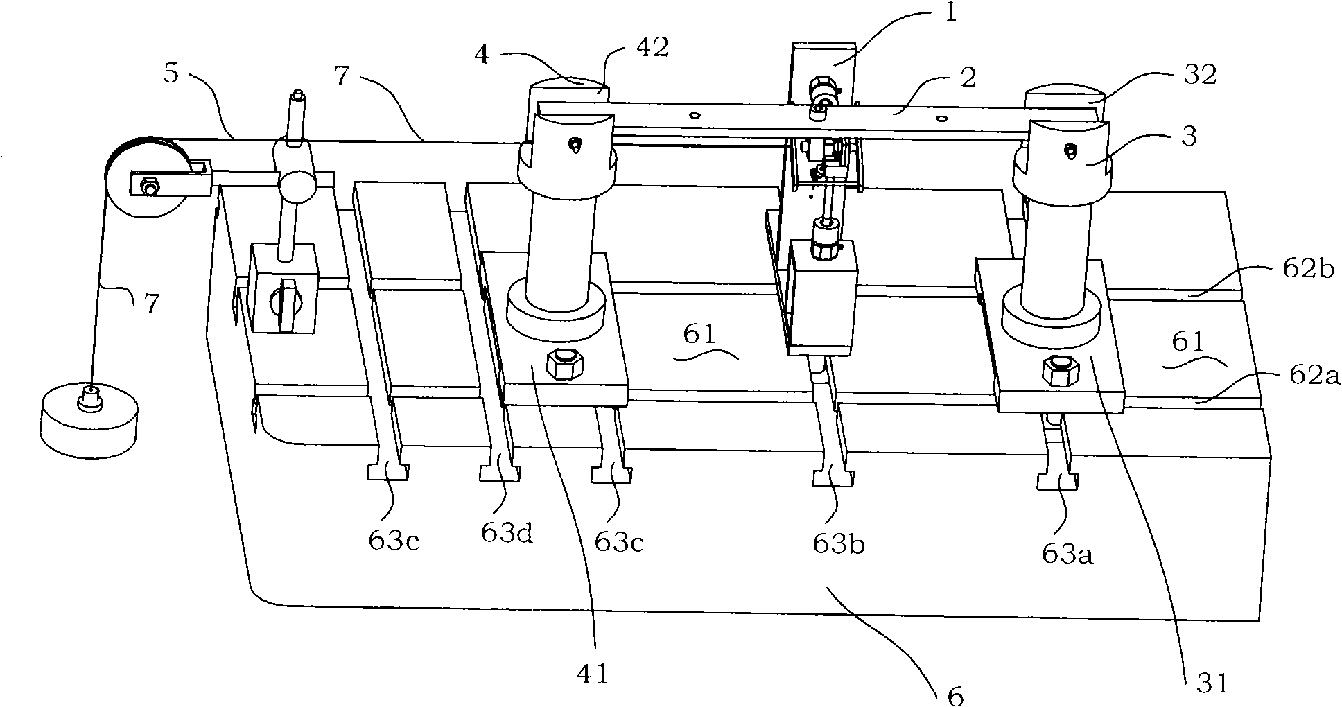
[0022] see figure 1 As shown, the present invention is a test device suitable for contact stiffness on the contact surface of a blade with a dry friction damping structure. The contact stiffness test device includes a friction test assembly 1, a positive pressure loading assembly 5, a simply supported beam 2, Support 3, left support 4, base 6; simply supported beam 2 is installed in the U-shaped groove of right support 3 and left support 4, friction test component 1, positive pressure loading component 5, right support 3, left support 4 are installed on the base 6.

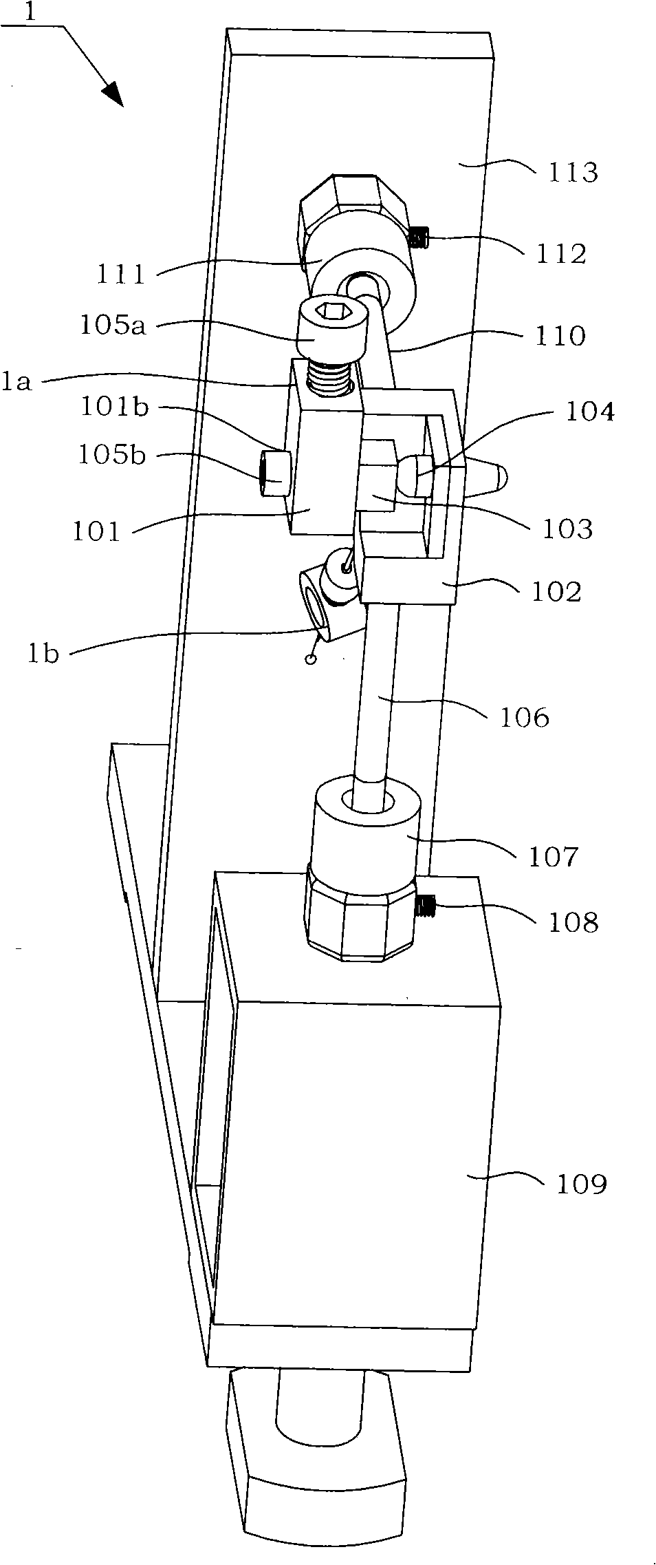
[0023] see figure 2 , figure 2 A. figure 2 B. figure 2 C. figure 2 As shown in D, the friction test assembly 1 includes a friction block assembly 1a, a tension loading assembly 1b, a transverse force test assembly, a longitudinal force test assembly, a T-shaped bracket 113, and a retur...


PUM


Abstract

The invention discloses a device for testing contact rigidity, and comprises a friction force testing component, a positive pressure loading component, freely supported beams, a right support, a left support and a base, wherein the freely supported beams are installed in U-shaped grooves of the right support and the left support; the friction force testing component, the positive pressure loading component, the right support and the left support are arranged on the base. When loaded with an initial positive pressure and a shock excitation load, the device for damping test can test the parameters of the tangential contact rigidity of a contact surface, such as different contact surface shapes, different initial positive pressures, the properties of different experiment sample materials, etc. and analyze the rule of influence of the contact surface shape, the initial positive pressure and the experiment sample material on the contact rigidity.

Description

technical field [0001] The invention relates to a testing device suitable for the contact stiffness on the contact surface of a blade with a dry friction damping structure. Background technique [0002] Dry friction damping technology is a very effective vibration reduction method between blades. Practice has proved that using damping nodes to increase structural damping is a very economical and effective method. It can not only weaken the vibration stress of blades, but also increase the blade system. Aeroelastic stability. In an aeroengine, the blade's ability to withstand vibrational stresses due to resonance or flutter is almost entirely dependent on the effect of interfacial dry friction damping. According to the data, 90% of the damping in a composite structure comes from its joints, and the damping characteristics of the joints come from the dry friction between the joints. Due to the insensitivity of dry friction damping to temperature changes, simple structure and...

Claims


Application Information

Patent Timeline
IPC IPC(8): G01N3/00
Inventor 马艳红洪杰陈璐璐朱彬李迪
Owner BEIHANG UNIV
Why Eureka
Try Eureka