Composite refrigeration method and device for high-power electric semiconductor device

A technology for power semiconductors and cooling devices, which is applied in the fields of semiconductor devices, semiconductor/solid-state device components, and electric solid-state devices, etc. The problem of large temperature difference of the radiator can save one-time investment, improve work efficiency and heat dissipation effect, and improve cooling efficiency.

Active Publication Date: 2013-01-02
SHANGHAI MUNICIPAL ELECTRIC POWER CO +1
View PDF0 Cites 0 Cited by
  • Summary
  • Abstract
  • Description
  • Claims
  • Application Information

AI Technical Summary

Problems solved by technology

[0016] The disadvantages of oil cooling are: ① high cost; ② low flammability and heat dissipation capacity, which is caused by the high viscosity and low flow rate of oil
[0022] According to the above analysis, although it is safe to use self-cooling and air-cooling cooling methods for power semiconductor devices, the heat transfer speed is slow, and the temperature difference between the two ends of the thyristor and the radiator is large, which restricts the cooling effect of high-power devices; Leakage, corrosion, discharge and other safety issues; the cost of oil cooling is high, and the heat dissipation effect is not satisfactory; the use of heat pipes has many advantages, but it needs the cooperation of a lower ambient temperature at the condensing end to fully exert its heat dissipation effect, otherwise it will not It is easy to meet the heat dissipation requirements of large-capacity power devices, which also restricts the application of heat pipes in the cooling of high-power power electronic devices to a certain extent

Method used


Image

  • Composite refrigeration method and device for high-power electric semiconductor device
  • Composite refrigeration method and device for high-power electric semiconductor device
  • Composite refrigeration method and device for high-power electric semiconductor device

Examples


Embodiment

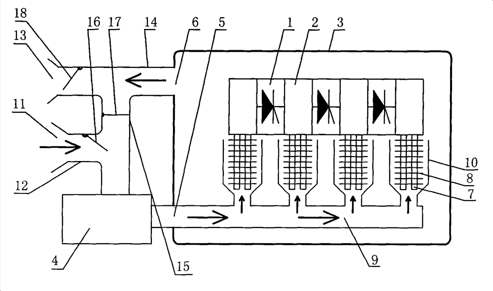
[0102] The system flow chart shown in Figure 5 is used. Since it is an engineering drawing, the marks, codes and meanings used in the drawing are marked according to the requirements and conventions of engineering drawings and national standards.

[0103] In the figure, the cold air (marked as fresh air) enters through the cold air pipe and the first electric control valve FM14, passes through the filter GLQ, the surface cooler BLQ, the water baffle DSB and the frequency conversion fan FJ in turn, and passes through the air supply temperature collector. The air supply main pipe of W1 and the air flow meter V and each air supply sub-channel equipped with the air supply sub-regulating valve FMn (n=1~11) are forced / directly transported to each cooling rib / fin group CU n(n =1~11).

[0104] In order to obtain a better operation / cooling effect, surface temperature collectors Wn (n=2-11) are arranged on each power semiconductor device.

[0105] After the heat absorption, the hot air...


PUM


Abstract

The invention discloses a compound cooling method for a high-power power semiconductor device, pertaining to the field of semiconductor devices. A heat pipe with groups of radiating ribs / wing panels is arranged on a radiating module, a low-temperature cooling gas is forcedly / directly transmitted to various groups of radiating ribs / wing panels, and the cooling gas is utilized to constitute electrical insulating layers between air supply air distribution ducts and various groups of radiating ribs / wing panels. The invention further provides a compound cooling device which utilizes the method andis provided with a combined air-conditioning box body, an air processing device and an air suction / exhaust pipeline, an air inlet and an air outlet are arranged on the air-conditioning box body, the air processing device is connected with the air suction / exhaust pipeline, the air outlet end thereof is connected with the air inlet of the air-conditioning box body, the air outlet of the air-conditioning box body is connected with the air suction / exhaust pipeline, an air supply main pipe is arranged at the air inlet in the air-conditioning box body, and the separate air supply air distribution ducts are respectively correspondingly arranged between the air supply main pipe and the various groups of radiating ribs / wing panels. The compound cooling method overcomes the shortcomings of the traditional cooling modes, and the system structure is simpler.

Description

technical field [0001] The invention belongs to the field of semiconductor devices, and in particular relates to a cooling device / system for power electronic devices (such as high-power thyristors). Background technique [0002] With the development of power electronics technology, more and more high-power power electronic devices (also known as power semiconductor devices) are used in static var compensation devices. [0003] During the working process of power electronic devices, the "junction temperature" increases due to the heat generated by various losses. [0004] The power electronic device is a semiconductor device with a relatively small thermal equivalent and is sensitive to heat generation. Almost all its parameters are related to thermal characteristics. Therefore, excessive "junction temperature" will cause damage to the normal working condition of the component and affect its Stability and reliability of operation. In order not to make its "junction temperat...

Claims


Application Information

Patent Timeline
Patent Type & Authority Patents(China)
IPC IPC(8): H01L23/34
CPCH01L2924/0002
Inventor 倪裕康郑斌毅陈金华余波
Owner SHANGHAI MUNICIPAL ELECTRIC POWER CO
Why Eureka
Try Eureka