Mould component for concrete filling

A tire mold and component technology, applied to building components, on-site preparation of building components, building construction, etc., can solve the problems of high cost and heavy weight

Inactive Publication Date: 2008-12-10
邱则有
View PDF1 Cites 8 Cited by
  • Summary
  • Abstract
  • Description
  • Claims
  • Application Information

AI Technical Summary

Problems solved by technology

Due to the heavy weight and high cost of the above types of thin-walled cavity c

Method used


Image

  • Mould component for concrete filling
  • Mould component for concrete filling
  • Mould component for concrete filling

Examples


Embodiment Construction

[0040] The present invention will be further described below in conjunction with the accompanying drawings and embodiments.

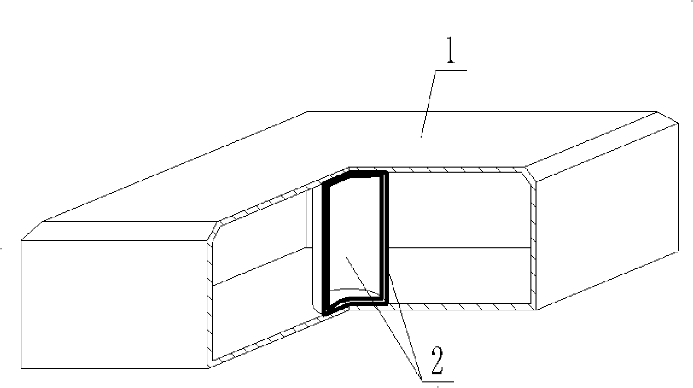
[0041] The invention, as shown in the accompanying drawings, comprises a closed casing 1 characterized in that at least one air bag 2 supports the casing. In each accompanying drawing, 1 is a closed shell, and 2 is an air bag. In the following accompanying drawings, those with the same number have the same description. Such as figure 1 As shown, the tire mold member for concrete filling includes a closed shell 1, which is characterized in that the shell is supported by an air bag 2.

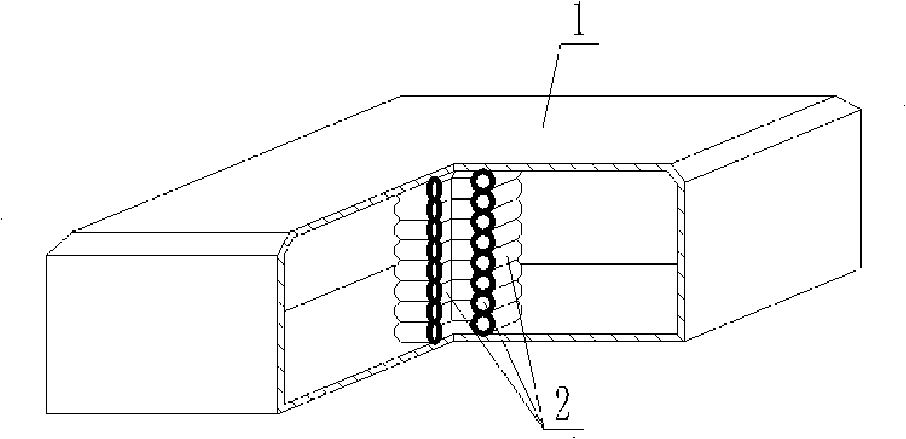
[0042] The present invention is also characterized in that the airbag 2 is a supporting airbag. Such as figure 2 Shown, its described airbag 2 is a supporting airbag.

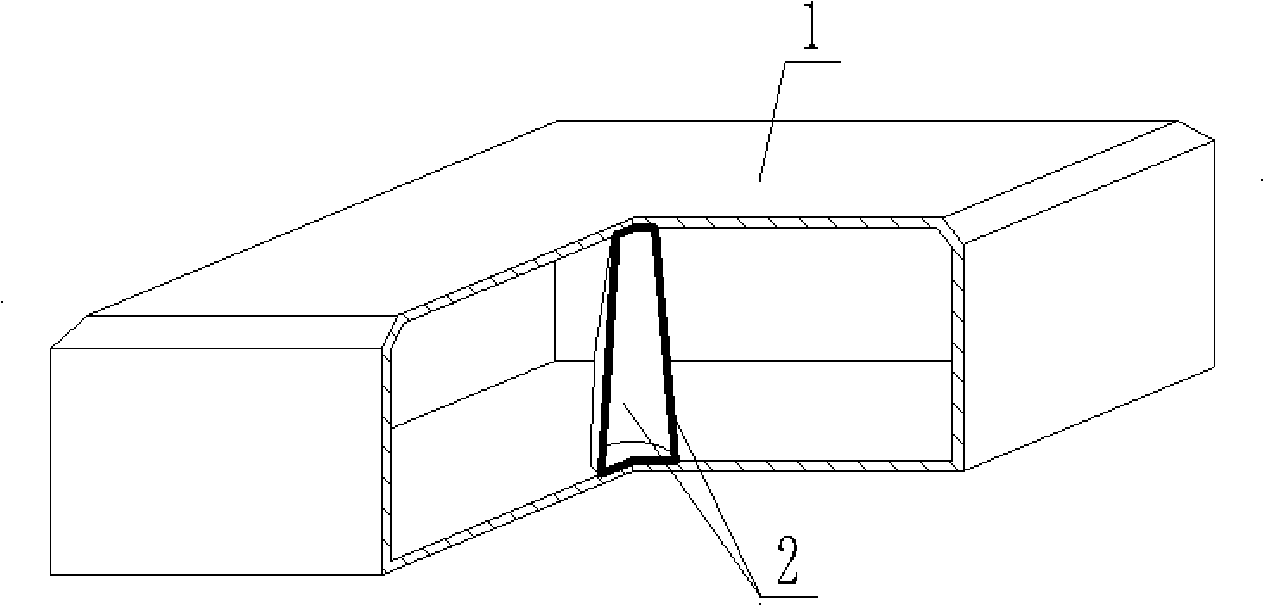
[0043] The present invention is also characterized in that the airbag 2 is a pier-type airbag. Such as image 3 Shown, its described air bag 2 is a pier type air bag.

[0044] The present invention is...


PUM


Abstract

A moulding bed member used for concrete filling comprises a closed outer casing (1). The moulding bed member is characterized in that: at least one air bag (2) is used to support the outer casing. Therefore, the moulding bed member can be aerated and mounted on a construction site, thereby ensuring convenient transportation, greatly reducing transportation cost and reinforcing the impact resistance, and increasing the mechanical property and the overall strength of the moulding bed member; moreover, because the inside of the moulding bed member adopts an air-bag structure, the member has light weight, low cost and excellent shock resistance along with simple production and convenient carrying and construction, thereby achieving the aim of the invention. The moulding bed member is suitable to be used in various floors, roofs, wall bodies and base slabs made of castinplace concrete as well as structures of road-bridge engineering, and is particularly suitable to be used in hollow beamless floor.

Description

(1) Technical field [0001] The invention relates to a tire mold member for concrete filling. (2) Background technology [0002] At present, in the prior art, the thin-walled cavity components used for cast-in-place reinforced concrete hollow slabs include paper tubes, plastic tubes, metal hollow tubes, hard thin-walled tubes, thin-walled membrane shell components, mandrels, etc. These thin-walled cavity components are mainly considered to evacuate the concrete to reduce the weight of the floor slab. For example, the patent No. 99249755.8 is the utility model patent of "fiber-reinforced thin-walled tube for filling cast-in-place reinforced concrete", which consists of a hard thin-walled tube and plugs at both ends. Form a closed cavity, the cross section of the hard thin-walled tube and the shape of the plug can be round, square, trapezoidal or other irregular shapes. After the body is wound and formed, the single-layer or multi-layer fiber cloth pipe with cement slurry is ...

Claims


Application Information

Patent Timeline
IPC IPC(8): E04C1/00E04B5/36E04G11/04
Inventor 邱则有
Owner 邱则有
Why Eureka
Try Eureka