Magnetic sensor and production method thereof

A magnetic sensor and sensor technology, applied in the field of magnetic sensors, can solve the problems of low accuracy and tilted position accuracy, and achieve the effects of increasing productivity, reducing the number and improving the production yield.

Inactive Publication Date: 2008-12-17
RICOH KK
View PDF3 Cites 30 Cited by
  • Summary
  • Abstract
  • Description
  • Claims
  • Application Information

AI Technical Summary

Problems solved by technology

On the other hand, the accuracy of the relative positional relationship of the biaxial magnetic field detector with respect to the uniaxial magnetic field detector is determined by bending the flexible substrate, and therefore, the magnetization directions of the biaxial magnetic field detector and the uniaxial magnetic field detector The accuracy of the relative positional relationship of the two-axis magnetic field detector is lower than the accuracy of the relative positional relationship of the magnetization direction of the dual-axis magnetic field detector
In addition, in order to bend and fix the flexible substrate, a certain overlap width is required, and this results in a thick and large substrate member for fixing the flexible substrate
[0019] Uncertainty in the accuracy of the relative position between the three axes results in a tilt in the position accuracy obtained from the external magnetic field measurement output
However, the three-axis orientation sensors disclosed in Ref. 2 and Ref. 3 have limitations in this regard

Method used


Image

  • Magnetic sensor and production method thereof
  • Magnetic sensor and production method thereof
  • Magnetic sensor and production method thereof

Examples


no. 1 example

[0102] In this embodiment, the magnetic field detectors are arranged in the same inclined surface with a certain angle.

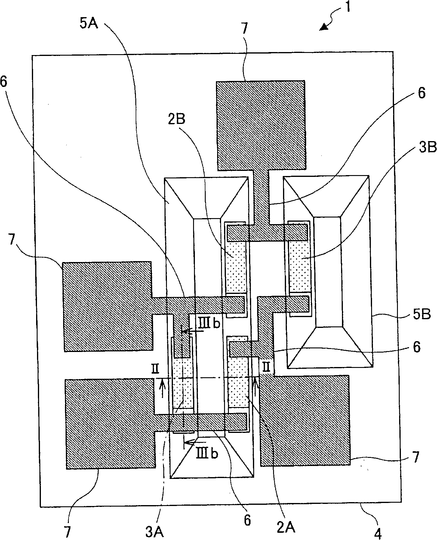
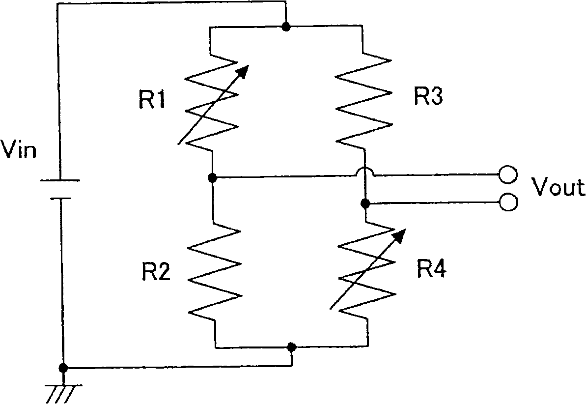
[0103] figure 1 It is a plan view schematically showing the configuration of the magnetic sensor according to the first embodiment in which magnetoresistance effect elements are connected to form a bridge circuit.

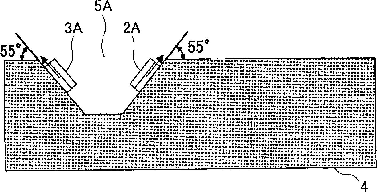
[0104] Such as figure 1 As shown, the magnetic sensor 1 of the present embodiment includes a substrate 4; a magnetic field detector 2A, a magnetic field detector 2B, a fixed resistor 3A, and a fixed resistor 3B arranged on the substrate 4; slots 5A and 5B (collectively referred to as “groove 5 ”); connection wiring 6 ; and bonding pad 7 .

[0105] For example, the magnetic field detectors 2A and 2B and the fixed resistors 3A and 3B are tunneling magnetoresistive (TMR) elements. Furthermore, the magnetic field detectors 2A and 2B and the fixed resistors 3A and 3B have the same layer configuration. In each of the fixed resistors 3A and 3B, a m...

no. 2 example

[0144] Similar to the first embodiment, in this embodiment, the magnetic field detectors are arranged in the same inclined surface with a certain angle.

[0145] Figure 6 A plan view schematically showing the configuration of a magnetic sensor according to a second embodiment in which magnetoresistance effect elements are connected to form a bridge circuit.

[0146] Such as Figure 6 As shown, the magnetic sensor 301 of this embodiment includes a substrate 304; a magnetic field detector 302A, a magnetic field detector 302B, a fixed resistor 303A, and a fixed resistor 303B arranged on the substrate 304; a groove 305; a connection wiring 306; and a bonding pad 307.

[0147] In the magnetic sensor 301, the fixed resistor 303A and the fixed resistor 303B are arranged on the same surface on which the bonding pad 307 is formed.

[0148] Here, for example, the magnetic field detectors 302A and 302B and the fixed resistors 303A and 303B are tunneling magnetoresistive (TMR) element...

no. 3 example

[0164] In this embodiment, the magnetic field detector and the fixed resistor are arranged in the inclined surface of the same slot.

[0165] Figure 8 A plan view schematically showing the configuration of a magnetic sensor according to a third embodiment in which magnetoresistance effect elements are connected to form a bridge circuit.

[0166] Figure 9 along Figure 8 Sectional view of line XVII-XVII.

[0167] Such as Figure 8 As shown, the magnetic sensor 401 of this embodiment includes a substrate 404; a magnetic field detector 402A, a magnetic field detector 402B, a fixed resistor 403A, and a fixed resistor 403B arranged on the substrate 404; a groove 405; a connecting wiring 406; and a bonding pad 407.

[0168] In the magnetic sensor 401 , a magnetic field detector 402A, a magnetic field detector 402B, a fixed resistor 403A, and a fixed resistor 403B are arranged within the inclined surface of the same groove 405 .

[0169] Here, for example, the magnetic field ...


PUM


Abstract

A magnetic sensor is disclosed that has plural axes at the same time, able to be fabricated in a small number of steps. The magnetic sensor includes a substrate; and plural sensor bridge circuits each including a pair of magnetic field detectors and a pair of fixed resistors on the substrate, the pair of the magnetic field detectors and the pair of the fixed resistors being connected to form a bridge circuit, each of the magnetic field detectors being formed of a magneto-resistance effect element, and magnetization directions of the magnetic field detectors intersect with each other in a three-dimensional manner. The substrate has plural inclined surfaces, normal directions of the inclined surfaces intersect with each other in a three-dimensional manner, and the pair of the magnetic field detectors in each of the sensor bridge circuits is arranged on the same inclined surface.

Description

technical field [0001] The present invention relates to a magnetic sensor using a magnetoresistive element and a manufacturing method of the magnetic sensor. Background technique [0002] In the related art, there are various types of sensors having magnetoresistive elements, and such sensors include using magneto resistance (magneto resistance) effect elements (MR elements), magneto impedance (magneto impedance) elements (MI elements) , fluxgate sensor (fluxgate sensor), semiconductor Hall effect sensor and other sensors. [0003] For example, considering MI sensors, since MI elements (magnetoresistive elements) are used, it is easy to make MI sensors thin and small, and further improvements are being made. [0004] As for the MR element, when a high-frequency current flows in the MR element, the high-frequency impedance of the MR element changes with the magnetic field, and by utilizing the change of the high-frequency impedance caused by the magnetic field, the magnetic ...

Claims


Application Information

Patent Timeline
Patent Type & Authority Applications(China)
IPC IPC(8): H01L27/22H01L21/82H01L21/822G01R33/09G01R33/02H01L43/08H01L43/12
CPCG01R33/0047G01R33/09H10N30/80H10N50/10H10N50/01
Inventor 安住纯一高太好布施晃广
Owner RICOH KK
Why Eureka
Try Eureka