
Electric heating tube component and manufacturing method thereof

The technology of an electric heating tube and its manufacturing method is applied in the electric heating tube component with enamel protective layer and its manufacturing field, which can solve the problems that cannot meet the production needs, the enamel coating is not covered, and the scale is accumulated at the end. Life extension, long service life, effect of improving service life

Active Publication Date: 2008-12-17
法罗力热能设备(中国)有限公司
View PDF0 Cites 12 Cited by
  • Summary
  • Abstract
  • Description
  • Claims
  • Application Information

AI Technical Summary

Problems solved by technology

[0003] At present, there is a heating tube on the market that is coated with an enamel coating on the surface of the metal tube to prevent the above situation from happening. Although it has a certain effect, the enamel coating does not cover the entire outer surface of the metal tube. When the product After a long time of use, scale will still accumulate on the tip
In addition, because the heating tube generally needs to measure the temperature to control its work, the temperature measuring tube is not far from the heating tube. The temperature measuring tube of the current product also has the problem of accumulating scale. After a long time of use, its temperature measurement is not accurate. imperfect
[0004] In addition, the existing manufacturing method of adding an enamel protective layer on the electric heating tube is to sinter the enamel paint coated on the outer surface of the metal tube into a dense and solid enamel layer by energizing itself after dipping the enamel paint. However, the production efficiency of this method is low and cannot meet the needs of production.

Method used


Image

  • Electric heating tube component and manufacturing method thereof
  • Electric heating tube component and manufacturing method thereof

Examples


Embodiment Construction

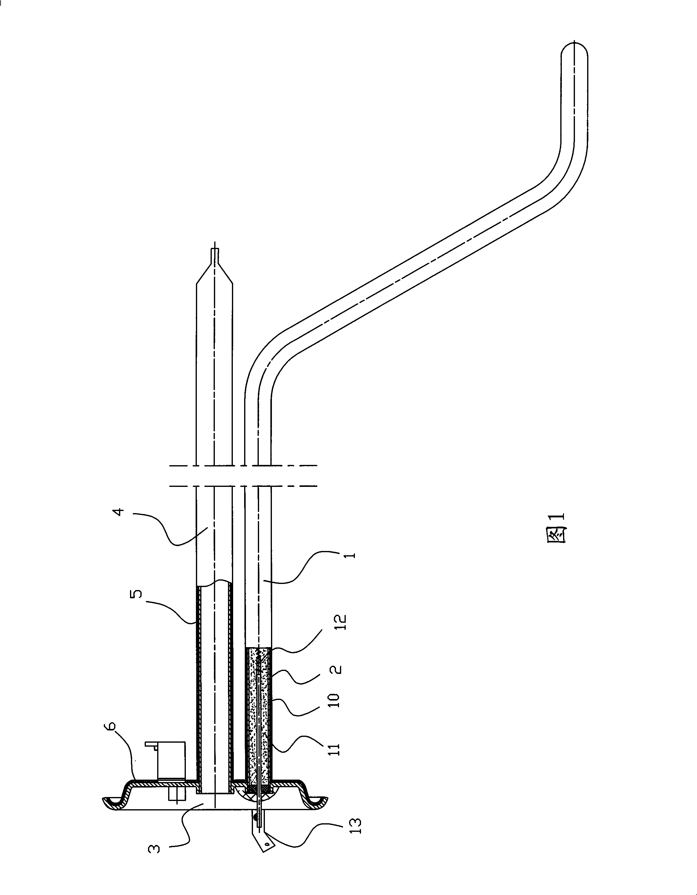
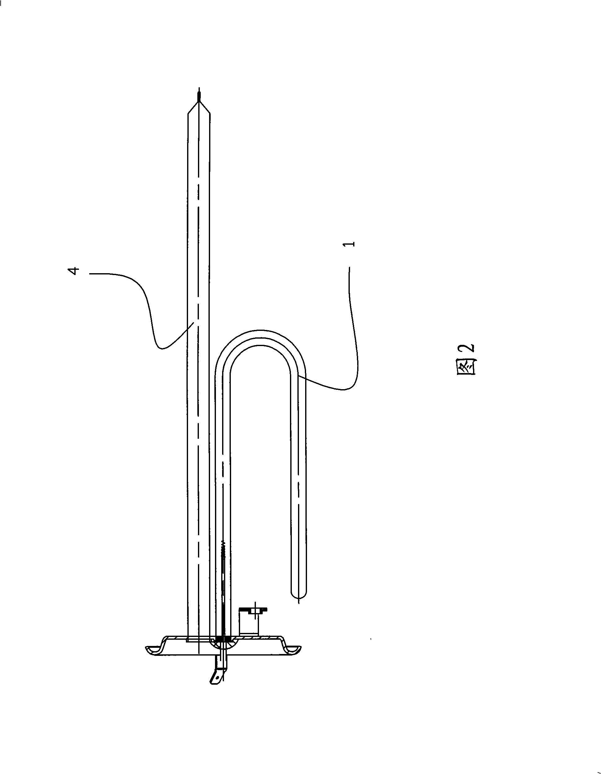
[0022] Referring to Fig. 1, an electric heating tube assembly of the present invention includes a heating tube 1, and the heating tube 1 includes a metal tube 10, and an electric heating wire 12 is passed through an insulating and heat-conducting material 11 inside the metal tube 10, and the heating tube 1 The outer surface of the metal tube 10 is covered with a protective layer of enamel 2 . Wherein, the metal pipe 10 can be an iron metal pipe of a specific shape as shown in Figure 1, of course, the metal pipe can also be another shape as shown in Figure 2, and the two ends of the iron metal pipe are protruded with heating wires 12 Connect the lead terminal 13.

[0023] Further, in order to facilitate the installation of the heating tube assembly on the inner tank of the electric water heater, the heating tube 1 is installed on a flange 3. In addition, in order to detect the real-time temperature of the heated liquid at the same time, the temperature of the heating tube can b...


PUM


Abstract

The invention discloses an electric heating pipe assembly and a manufacturing method thereof. The electric heating pipe assembly comprises a heating pipe which comprises a metal tube, the metal tube is provided with heating cords made of insulated heat conduction material, and the outer surface of the metal tube of the heating pipe is covered with an enamel protective layer. The electric heating pipe is absorbed through static electricity, the outer surface of the metal tube is coated with an enamel layer, so that the coated enamel layer covers the outer surface of the metal tube completely; the electric heating pipe coated with the enamel layer is sintered at high temperature, to form a compact and firm enamel protective layer by the enamel paint coated on the surface of the metal tube. Because the outer surface of the metal tube is coated with the enamel protective layer completely, the contact of the heated pipe liquid and the metal is stopped completely, thereby improving the corrosion resistance of the surface of the metal tube and improving the service life of the electric heating pipe; moreover, the production efficiency is high, and the product quality is stable and reliable. The electric heating pipe assembly of the invention can be widely applied to the domestic and industrial fields.

Description

technical field [0001] The invention relates to an electric heating tube assembly and a manufacturing method thereof, in particular to an electric heating tube assembly with an enamel protective layer and a manufacturing method thereof. Background technique [0002] At present, the electric heating tube components currently used in electric water heaters are directly heated by contact with water, and the water contains various impurities such as Cl- ions and Ca2+. During the heating process, the electric heating elements are easy to absorb various impurities and cause corrosion, and Limescale builds up. In this way, not only will the life of the electric heating tube be shortened, but the heating efficiency will be significantly reduced after a period of use. [0003] At present, there is a heating tube on the market that is coated with an enamel coating on the surface of the metal tube to prevent the above situation from happening. Although it has a certain effect, the ena...

Claims


Application Information

Patent Timeline
Patent Type & Authority Applications(China)
IPC IPC(8): H05B3/82C23D5/04
Inventor 周鹏吴维荣韩宝东林志亮易伟文区兆明
Owner 法罗力热能设备(中国)有限公司
Learn More