Sinusoidal angled rotary cutting tool

A tool and cutting edge technology, applied in the field of low-resonance end mills, can solve the problem of weakening shear force in local areas

Active Publication Date: 2008-12-17
韩国养志园有限公司
View PDF0 Cites 18 Cited by
  • Summary
  • Abstract
  • Description
  • Claims
  • Application Information

AI Technical Summary

Problems solved by technology

The end mill must also be easy to manufacture a

Method used


Image

  • Sinusoidal angled rotary cutting tool
  • Sinusoidal angled rotary cutting tool
  • Sinusoidal angled rotary cutting tool

Examples


Embodiment Construction

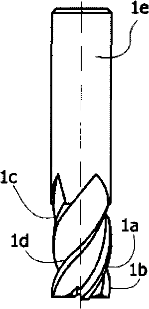
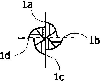
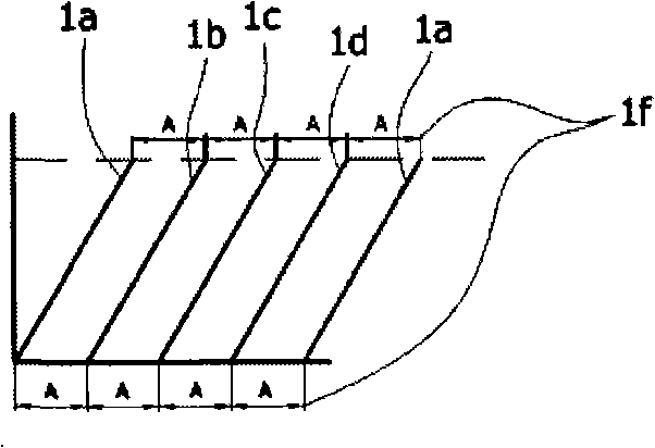
[0052] Figure 5A to Figure 5C An end mill having four cutting edges according to a first embodiment of the present disclosure is shown. The end mill has sinusoidal cutting edges equally spaced around the circumference of the cutting surface.

[0053] The end mill comprises a cylindrical tool body 100 having a longitudinal central axis 101 . The end mill in this preferred embodiment can be used, for example, in the precision machining industry. The end mill includes a single fluted cutting end 102 oppositely formed on a cylindrical body and a shank end 5e having a shank extending along a longitudinal central axis. Those of ordinary skill in the art will appreciate that while a flat nose end mill (i.e., an end mill with a flat end cutting surface) is shown, any other end is possible, such as a spherical end, ball nose, Countersunk end (chamfer end) and so on. The disclosed end mills are also not limited to cutting a single type of material. This preferred embodiment can be...


PUM


Abstract

It is the object of the present disclosure to provide an improved end mill that can be easily manufactured, reduces cutting forces on the driving tool, limits chatter at high rotation speeds, has better stability, produces smoother cutting surfaces, and has less natural resonating frequencies while in use to permit operation of the end mill over a wider range of operating conditions. The end mill is equipped with a series of sinusoidal cutting edges with a single long pitch arranged regularly or irregularly along the circumferential cutting surface. In another embodiment, the pitch, the cutting angle of the datum line of the sinusoidal cutting edges and the amplitude of the sinusoidal function can be varied.

Description

technical field [0001] This disclosure relates to the field of rotary cutting tools, and to a class of tools known as end milling cutters. More specifically, the present disclosure relates to a low resonance end mill having a plurality of sinusoidal circumferential cutting edges. Background technique [0002] High-speed rotating cutting tools are used in metal cutting processes. One of the main goals in designing end mills is to create cutting surfaces that remove large amounts of material quickly while leaving a relatively smooth surface on the workpiece. It is also desirable to minimize cutting forces to reduce the power required to drive the tool. [0003] A smooth surface is obtained if the cutting surface of the end mill remains vertical and does not vibrate during use. Vibration of a long straight body produces undesired bending along its major axis. Vibration (often also called chatter or chatter) of a rotating cutting tool is produced by the tool body being excit...

Claims


Application Information

Patent Timeline
IPC IPC(8): B23B27/02
CPCB23C5/10B23C2210/0414B23C2210/0485B23C2210/088B23C2210/282B23C2210/54B23C2250/16Y10T407/1946Y10T407/1948Y10T407/1962B23B27/00B23B27/02B23B27/14
Inventor 宋镐根
Owner 韩国养志园有限公司
Why Eureka
Try Eureka