
Central receiving type high temperature solar heat collecting system of light funnel light gathering orienting light transmission

A light funnel and central technology, which is applied in the application of optical technology and the utilization of solar energy concentration, efficient solar energy concentration, high-efficiency light guide and high-temperature solar heat collection, can solve the problem of limited energy accumulation, large flow resistance of working fluid, and device It cannot be made too large, so as to achieve the effect of easy technology, simple control strategy and saving construction costs

Inactive Publication Date: 2008-12-24
BEIJING INSTITUTE OF TECHNOLOGYGY
View PDF0 Cites 10 Cited by
  • Summary
  • Abstract
  • Description
  • Claims
  • Application Information

AI Technical Summary

Problems solved by technology

However, the above three methods have their own disadvantages. The disadvantage of large parabolic reflective focusing is that the device cannot be made too large, so the gathered energy is limited.
The disadvantage of large trough parabolic focusing is that there are too many and too long heat transfer pipelines, complex structure, large heat loss, large flow resistance of working fluid, and the temperature cannot be gathered too high, generally only about 250-350 °C; central tower focusing The temperature of the method can be very high, reaching about 500°C or higher, but it needs to build a tower tens of meters or even hundreds of meters high, and each reflector needs to track the sun separately, so the cost is very high

Method used


Image

  • Central receiving type high temperature solar heat collecting system of light funnel light gathering orienting light transmission
  • Central receiving type high temperature solar heat collecting system of light funnel light gathering orienting light transmission
  • Central receiving type high temperature solar heat collecting system of light funnel light gathering orienting light transmission

Examples


Embodiment Construction

[0013] The present invention will be further described below in conjunction with drawings and embodiments.

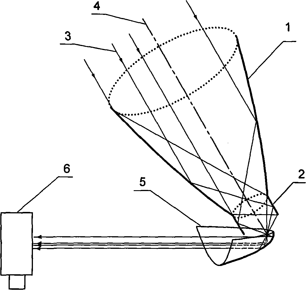
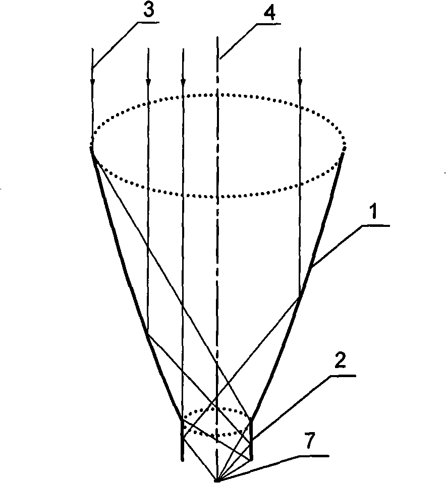
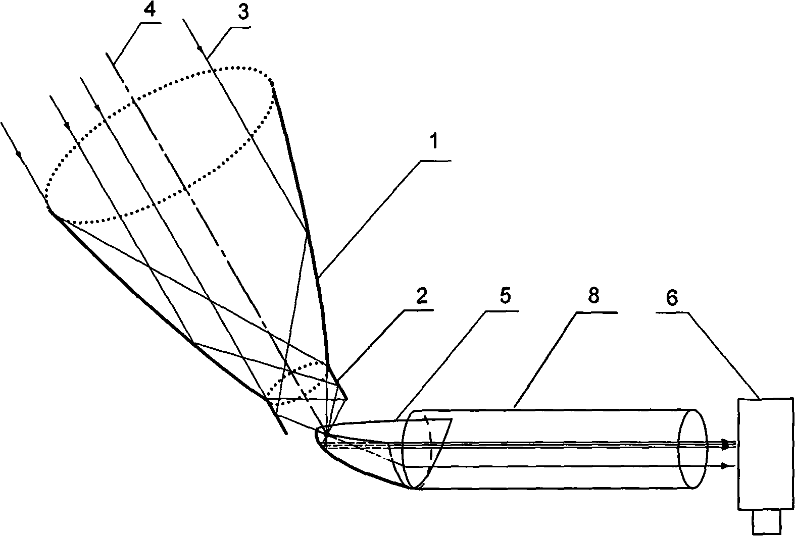
[0014] An optical funnel of the present invention concentrates light and transmits light centrally to receive high-temperature solar heat collection system is composed of one or more subsystems, 0 to more light guides and a central receiver; The light device 8 transmits to the central receiver 6 or directly transmits it to the central receiver 8 without passing through the light guide 8, and is converted into high-temperature heat energy by the central receiver 8. The subsystem consists of a rotating combined paraboloid 1, a cylindrical mirror reflecting surface 2 and a directional polarizer 5; the rotating combined paraboloid 1 and the cylindrical mirror reflecting surface 2 are connected into one body along the axial direction to form a focusing light funnel that follows the movement of the sun; the directional polarizer 5 is a paraboloid of revolution that cuts off 1...


PUM


Abstract

The invention relates to a high-temperature solar-energy heat-collecting system provided with the functions of light-assembling with a light funnel, directional light-transmission and central light-receiving, belonging to the optical technology application and solar-energy light-assembling application field. The invention comprises the light funnel provided with a point-focusing function, a directional polariscope and a central receiver which are sequentially arranged. The sunshine is assembled to form a point light supply through the light funnel, and the position of the point light supply overlaps a focus of the paraboloidal directional polariscope, and the sunshine is reflected by the directional polariscope and then is sent to the central receiver to be received. As the sending direction of the directional polariscope is adjustable, one central receiver can receive the sunshine which is from different directions and collected by a plurality of light funnels, thus forming the high-temperature heat energy.

Description

technical field [0001] The invention belongs to the field of optical technology application and solar energy concentration utilization, in particular to the technical field of solar energy efficient concentration, high efficiency light guide and high temperature heat collection and utilization of solar energy. It can also be used in the fields of convergence and propagation of radio waves. Background technique [0002] To achieve large-scale solar high-temperature heat collection, there are currently three general methods: large parabolic reflective focusing, large trough parabolic focusing, and central tower gathering. However, the above three methods have their own disadvantages. The disadvantage of large-scale parabolic reflective focusing is that the device cannot be made too large, so the gathered energy is limited. The disadvantage of large trough parabolic focusing is that there are too many and too long heat transfer pipelines, complex structure, large heat loss, la...

Claims


Application Information

Patent Timeline
IPC IPC(8): F24J2/00F24J2/07F24J2/10F24J2/46G02B17/06G02B27/00F24S20/20F24S23/70
CPCY02E10/40
Inventor 郑宏飞何开岩陶涛薛晓迪谢果
Owner BEIJING INSTITUTE OF TECHNOLOGYGY
Learn More