Novel carbon brush structure

A carbon brush, a new type of technology, applied in current collectors, electrical components, rotating current collectors, etc., can solve problems such as easy sparks, poor heat dissipation, offset of commutator and carbon rods, etc., and achieve the effect of easy heat dissipation

Inactive Publication Date: 2008-12-24
LG ELECTRONICS (TIANJIN) APPLIANCES CO LTD
View PDF0 Cites 9 Cited by
  • Summary
  • Abstract
  • Description
  • Claims
  • Application Information

AI Technical Summary

Problems solved by technology

[0008] The surrounding surface of the carbon rod in the prior art is a smooth plane, and the front end of the carbon rod is a smooth arc. The disadvantage of this structure is that the heat dissipation is poor, and the commutator and the carbon rod are offset when they are in contact with each other, which is easy to generate sparks; in addition, The powder generated by the friction between the commutator and carbon rods tends to stick to the armature, deteriorating the characteristics of the motor

Method used


Image

  • Novel carbon brush structure
  • Novel carbon brush structure
  • Novel carbon brush structure

Examples


Embodiment Construction

[0032] Below, a kind of novel carbon brush structure of the present invention is described in detail with reference to accompanying drawing and embodiment:

[0033] The components of the present invention and the existing carbon brushes with the same structure adopt the same symbols.

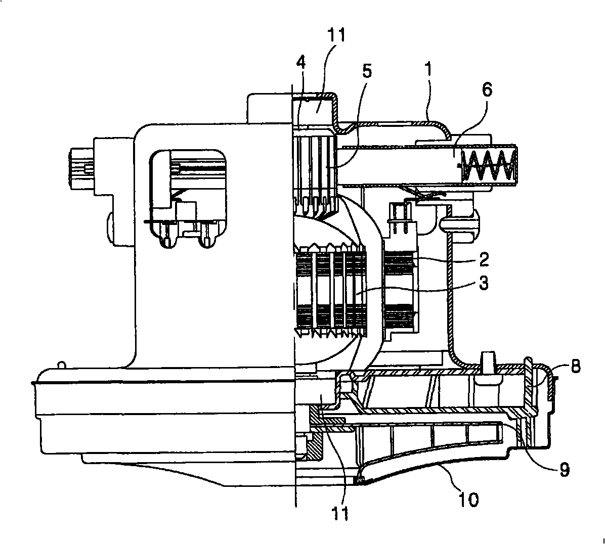
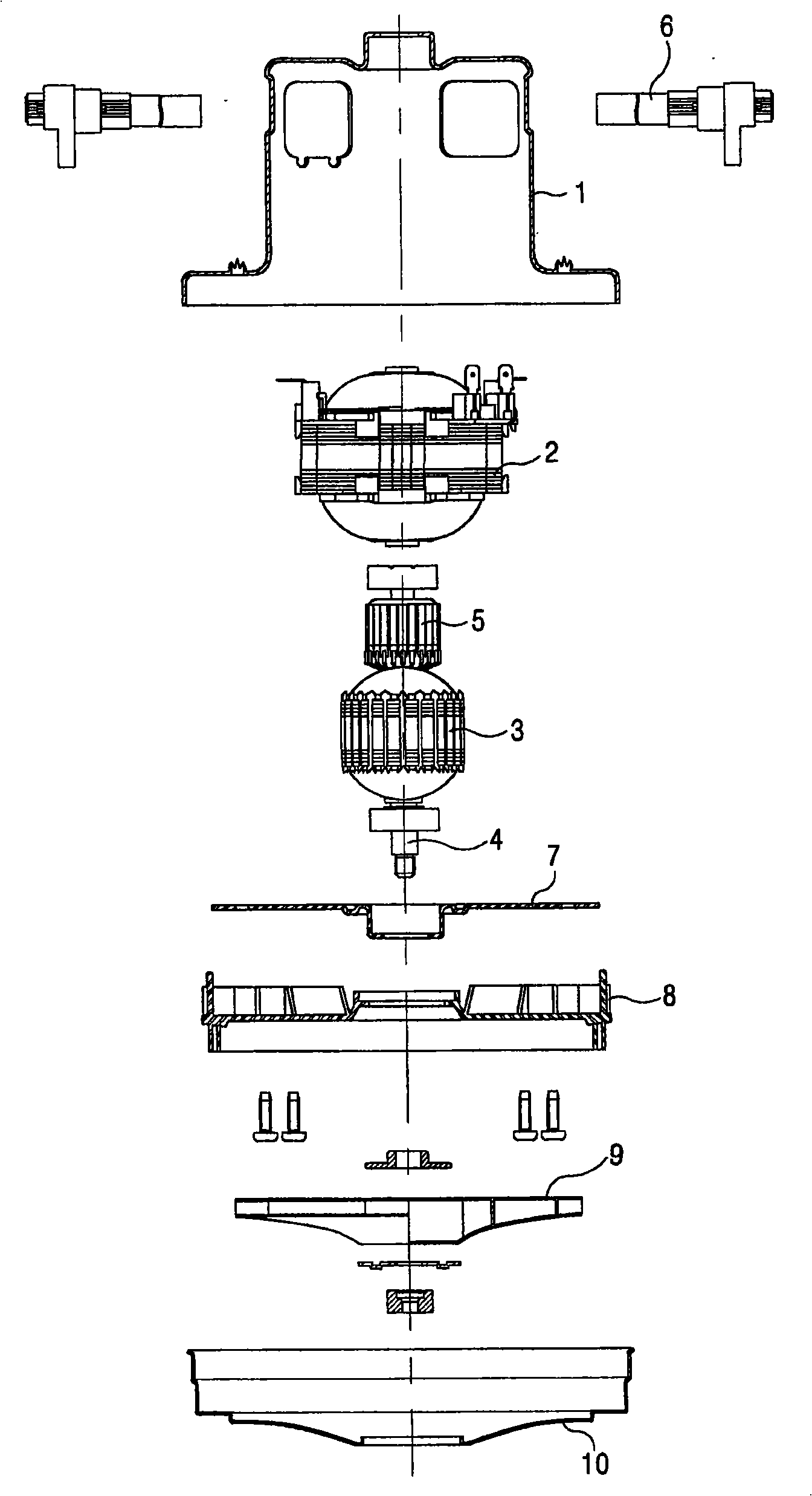
[0034] Such as figure 1 As shown in ~8, the single-phase motor includes a casing 1 with openings, a stator 2 is fixed inside the casing 1, and a rotor that can rotate at a certain distance from the inner peripheral surface of the stator 2 is provided on the inside of the stator 2. 3. A rotating shaft 4 is installed at the center of the rotor 3 . Bearings 11 are arranged on both ends of the rotating shaft 4, and the bearings 11 are fixed by the casing 1 and the wind cover 8 to make the rotating shaft 4 rotate.

[0035] On the upper side of the rotor 3, there is a commutation rectifier 5 that converts the supplied AC current into a DC current. On both sides of the commutation rectifier 5, there...


PUM


Abstract

The invention discloses a novel carbon brush structure, which comprises a support connected to one end of a copper sleeve, a plurality of heat dissipating holes formed on the copper sleeve, a carbon rod connected to the other end of the copper sleeve, a metal sheet arranged at the lower part of the copper sleeve and coming into contact with a connecting terminal, rectangular slots formed respectively at the top and at the bottom of the carbon rod along the length direction of the carbon rod, and a plurality of uniformly distributed grooves formed on the peripheral surface of the carbon rod. The carbon brush structure has the advantages that the heat dissipation is simple, and the powder generated by the friction between a commutator and the carbon rod can be easily blown off along the grooves so as to prevent the powder from adhering on an armature.

Description

technical field [0001] The invention belongs to a motor device, and in particular relates to a new carbon brush structure which is easy to dissipate heat and prevent the powder falling off the carbon rod from sticking to the armature. Background technique [0002] Generally speaking, a motor is a machine that converts electrical energy into kinetic energy. Such a motor can be divided into a rotary motor that converts electrical energy into rotary motion and a reciprocating motor that converts electrical energy into linear reciprocating motion. [0003] Electric motors are installed as power sources in almost all products used in households such as refrigerators, air conditioners, washing machines, electric fans, and vacuum cleaners. [0004] In order to make the motor rotate continuously, a commutation rectifier is used. The function of the commutation rectifier is to convert the current sequentially, so that the rotor can rotate in a certain direction at any position. [0...

Claims


Application Information

Patent Timeline
Patent Type & Authority Applications(China)
IPC IPC(8): H01R39/18H01R39/26H01R39/38
Inventor 刘勇
Owner LG ELECTRONICS (TIANJIN) APPLIANCES CO LTD
Why Eureka
Try Eureka