Indoor unit for air conditioner
An air-conditioning device and indoor unit technology, which is applied in the field of indoor units, can solve problems such as restrictions on the appearance design of the lower panel, and achieve the effects of improving maintainability, increasing market demand, and increasing the freedom of appearance design
- Summary
- Abstract
- Description
- Claims
- Application Information
AI Technical Summary
Problems solved by technology
Method used
Image
Examples
no. 1 example 〕
[0050]
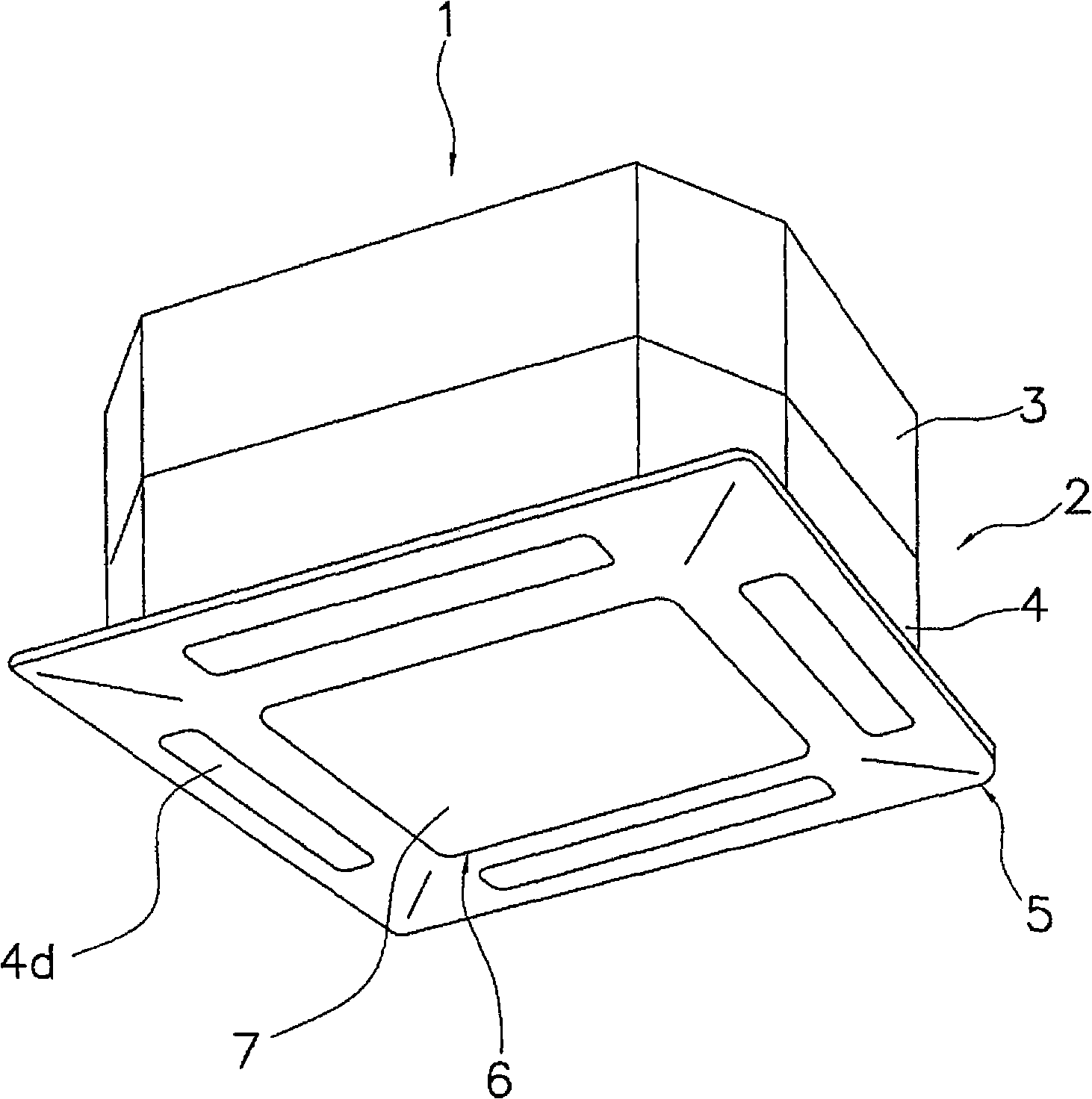
[0051] figure 1 is a perspective view of the appearance of the indoor unit according to the first embodiment of the present invention. The casing 2 of the indoor unit 1 is composed of a casing upper part 3 and a casing lower part 4, and is embedded in the ceiling when installed. In addition, a part of the housing lower part 4 is exposed from the ceiling, and this part is called the lower panel 5 . The lower panel 5 is provided with a suction port 6 through which air is sucked in, and an outlet 4d through which air is blown out.
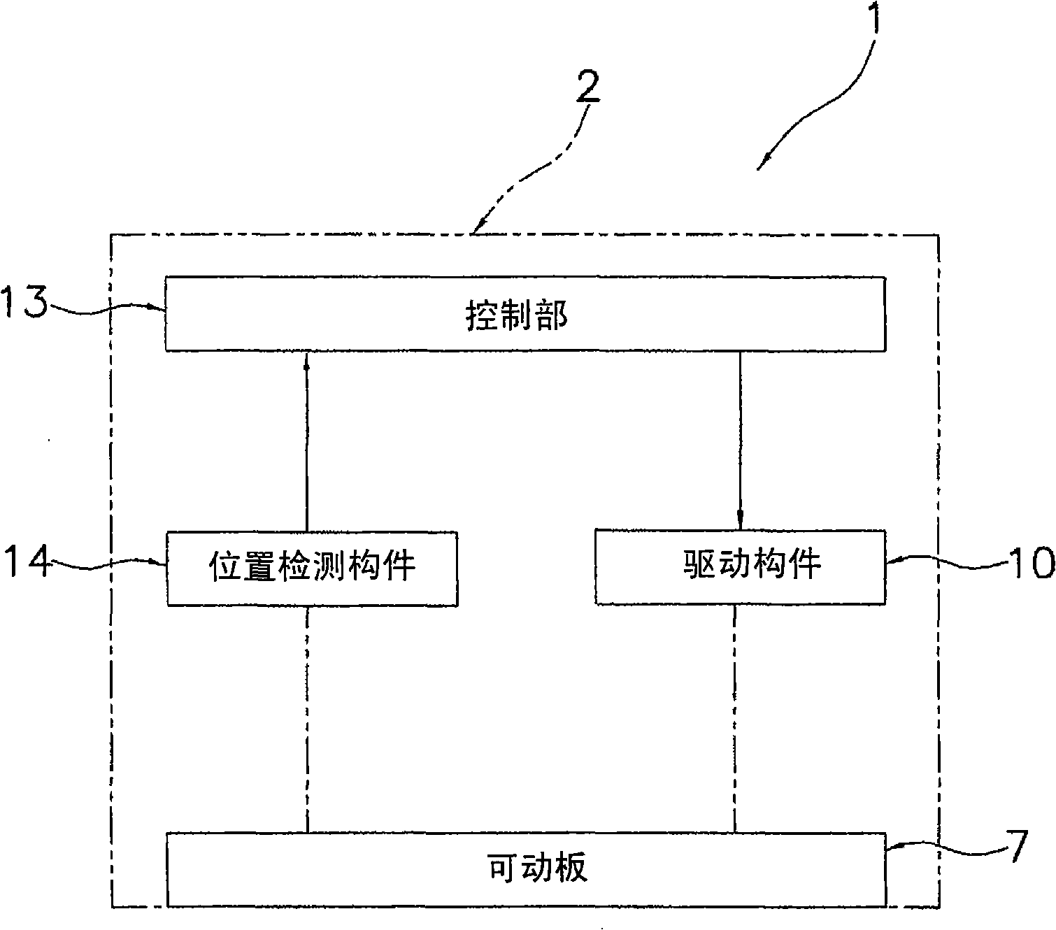
[0052] The movable plate 7 completely blocks the suction port 6 when the indoor unit 1 is stopped so that the suction port 6 is not exposed. figure 2is a block diagram of the action of the movable plate 7 , and the movable plate 7 can move to the inside of the shell 2 through the drive member 10 provided inside the shell 2 . The control unit 13 controls the drive member 10 to move or rotate the movable plate 7 . The position informatio...
no. 2 example
[0065]
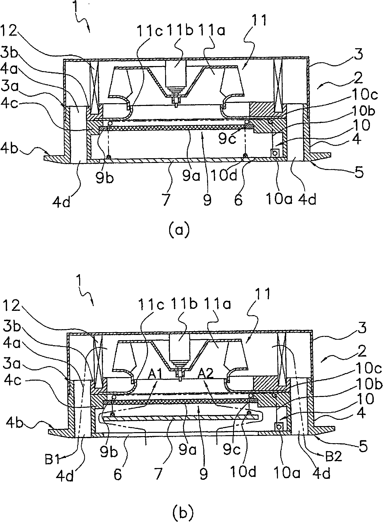
[0066] Next, a second embodiment of the present invention will be described. The same symbols are assigned to the same components as those of the first embodiment, and description thereof will be omitted. Figure 4 (a) is a cross-sectional view of the indoor unit of the second embodiment when the operation is stopped, Figure 4 (b) is a cross-sectional view of the indoor unit during operation.
[0067] The lower panel 25 is provided with a suction port 26 through which air is sucked in, and a blower port 4d through which air is blown out. The movable plate 27 completely blocks the suction port 26 so that the suction port 26 is not exposed when the indoor unit 21 is stopped.
[0068] The movable plate 27 and the filter 9 are connected by a connecting rod 27a while keeping a predetermined distance therebetween. The wire 10b extends vertically upward from a hook portion 10d attached to the filter 9, and is guided to the motor 10a via a plurality of pulleys 10c.
[...
no. 3 example
[0075]
[0076] Next, a third embodiment of the present invention will be described. The same symbols are assigned to the same constituent elements as those of the first embodiment, and description thereof will be omitted. Figure 5 (a) is a cross-sectional view of the indoor unit of the third embodiment when the operation is stopped, Figure 5 (b) is a cross-sectional view of the indoor unit during operation.
[0077] The lower panel 35 is provided with a suction port 36 through which air is sucked in, and an outlet 4d through which air is blown out. The movable plate 37 completely blocks the suction port 36 so that the suction port 36 is not exposed when the indoor unit 31 is stopped.
[0078] The movable plate 37 is formed of a plurality of small plate-shaped movable plates 37a to 37e. The small movable plates 37a to 37e can move in the vertical direction by the guide 39, but cannot move in the horizontal direction.
[0079] exist Figure 5 In (a), the right end of t...
PUM
 Abstract
Description
Claims
Application Information
 - R&D
- Intellectual Property
- Life Sciences
- Materials
- Tech Scout
- Unparalleled Data Quality
- Higher Quality Content
- 60% Fewer Hallucinations
Browse by: Latest US Patents, China's latest patents, Technical Efficacy Thesaurus, Application Domain, Technology Topic, Popular Technical Reports.
© 2025 PatSnap. All rights reserved.Legal|Privacy policy|Modern Slavery Act Transparency Statement|Sitemap|About US| Contact US: help@patsnap.com


