Combined speed reducer for stir can

A reducer and meshing technology, which is applied in cement mixing devices, clay preparation devices, chemical instruments and methods, etc., can solve the problems of uneven mixing and difficulty in meeting the mixing requirements of high-quality mortar, and achieve improved mixing uniformity, compact structure, Avoid easy loose effect

Inactive Publication Date: 2008-12-31
TIANJIN SPEED REDUCER
View PDF0 Cites 5 Cited by
  • Summary
  • Abstract
  • Description
  • Claims
  • Application Information

AI Technical Summary

Problems solved by technology

The disadvantage of this kind of mixing reducer is that the mixing is not uniform, and it is difficult to meet the mixing requirements of high-quality mortar

Method used


Image

  • Combined speed reducer for stir can

Examples


Embodiment Construction

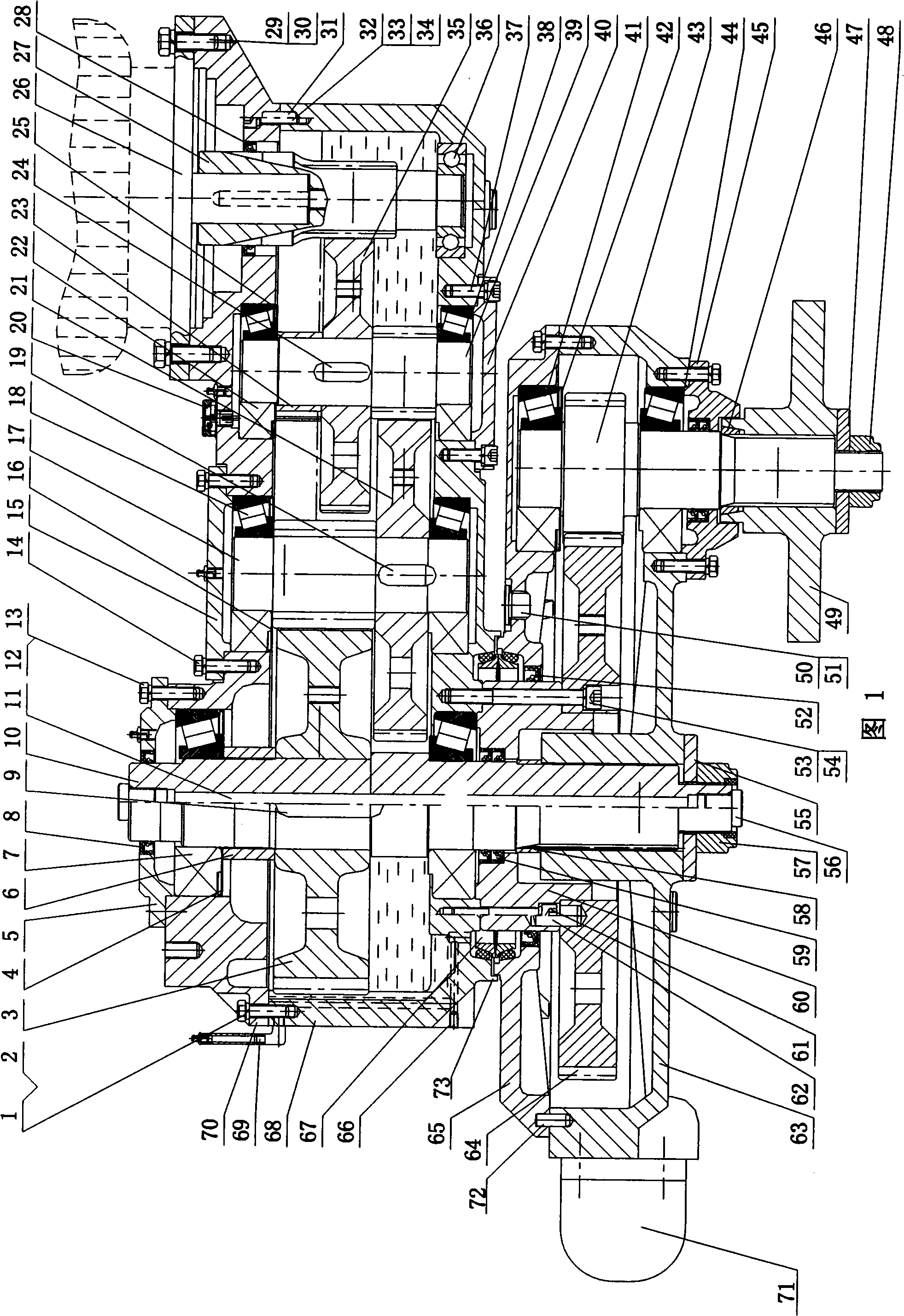
[0016] In order to further understand the invention content, characteristics and effects of the present invention, the following examples are given, and detailed descriptions are as follows in conjunction with the accompanying drawings:

[0017] Please refer to Fig. 1, on the upper case body 68 that oiler 69 is housed, by screw 1,32,33,34 and elastic washer 2, pin 31, upper case cover 70 is installed, has on the upper case cover and shows oil vent cap 20 , The side of the lower end of the upper casing is shaped on an oil circuit process hole, and a screw plug 66 is installed on the hole port. A hollow input gear shaft 27 is installed in the upper case through a bearing 36 and a skeleton oil seal 28 . The motor 26 that drives the hollow input gear shaft is installed by screw 29 and spring washer 30 on the upper case cover. In the upper box, the input gear shaft 39 and the input gear 35 meshing with the hollow input gear shaft are installed through the bearing 38, 22, the washe...


PUM


Abstract

The invention relates to a combined reducing machine used for a mixing tank, which is characterized in that an upper box body is internally provided with a hollow input gear shaft; the upper surface of an upper box cover is provided with a motor which drives the hollow input gear shaft; the upper box body is internally provided with an input gear shaft and an input large gear which is engaged with the hollow input gear shaft; the upper box body is internally provided with a middle gear shaft and a middle large gear which is engaged to the input gear shaft; the upper box body is internally provided with an output shaft and an output large gear which is engaged with the middle gear shaft; the lower end of the output shaft is provided with a lower box body and a lower box cover which rotate correspondingly to the output shaft; a transition sleeve which is fixed with the upper box body and concentric to the output shaft is arranged between the lower box body and the upper box body; the transition sleeve is fixedly provided with a solar wheel; the lower box body is internally provided with a planetary wheel shaft which is engaged with the solar wheel, and the lower end of the planetary wheel shaft extends out; the extension end spline of the planetary wheel shaft is provided with a mixing arm which rotates correspondingly to the planetary wheel shaft, thus leading the mixing arm to have revolution and rotation and improving the uniformity of the mixing; furthermore, the combined reducing machine used for a mixing tank has the advantages of simple and compact structure, convenient assembly and maintenance and easy manufacture.

Description

technical field [0001] The invention relates to a speed reducer arranged on a mixing tank truck in construction engineering, in particular to a combined speed reducer for a mixing tank. Background technique [0002] At present, with the rapid development of my country's construction industry, the demand for various mixing equipment continues to increase, and the functional requirements for its heart component, the reducer, are also getting higher and higher. The usual structure of the mixing tank is: the output shaft of the vertical or horizontal reducer directly drives the stirring blade to realize the stirring action, and the stirring blade is concentric with the output shaft of the reducer and only rotates. The disadvantage of this kind of mixing reducer is that the mixing is not uniform, and it is difficult to meet the mixing requirements of high-quality mortar. Contents of the invention [0003] In order to solve the technical problems existing in the known technolog...

Claims


Application Information

Patent Timeline
Patent Type & Authority Applications(China)
IPC IPC(8): B28C5/42
Inventor 张谦
Owner TIANJIN SPEED REDUCER
Why Eureka
Try Eureka