Turbomachine stator damper device

A machine stator and turbine technology, applied in the direction of stator, shock absorber, shock absorber, etc., can solve problems such as unbalanced blades, unbalanced use of turbines, and difficult implementation of processing technology, so as to increase structural damping, reduce costs, shorten Effect of development and commissioning time

Active Publication Date: 2008-12-31
SN DETUDE & DE CONSTR DE MOTEURS DAVIATION S N E C M A
View PDF1 Cites 12 Cited by
  • Summary
  • Abstract
  • Description
  • Claims
  • Application Information

AI Technical Summary

Problems solved by technology

This arrangement makes the machining process difficult due to the thickness of the blades
Furthermore, on the same impeller, there is a risk of an imbalance between the individual blades, resulting in unbalanced use of the turbine

Method used


Image

  • Turbomachine stator damper device
  • Turbomachine stator damper device
  • Turbomachine stator damper device

Examples


Embodiment Construction

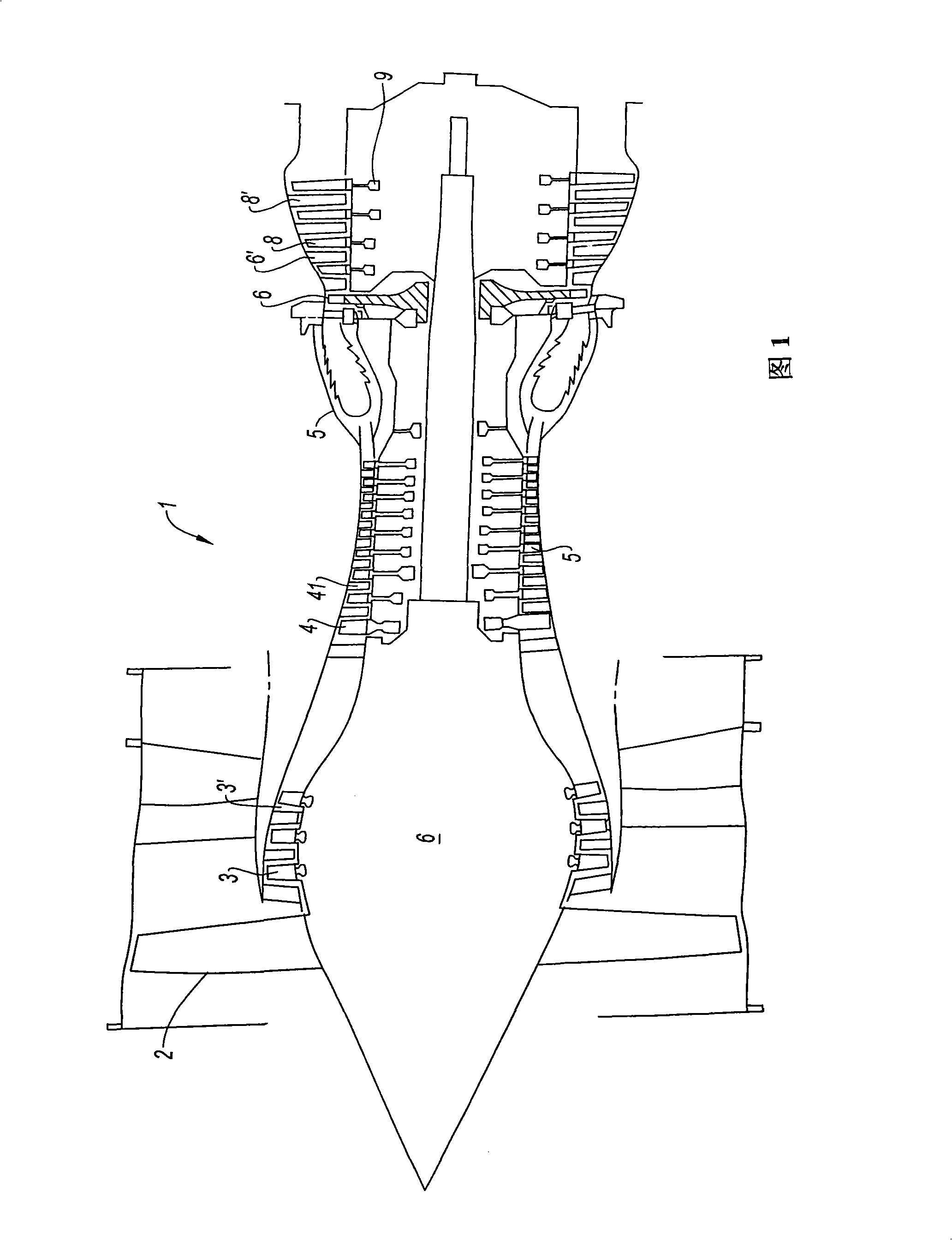
[0032] FIG. 1 is a schematic diagram of a turbine in the form of a twin-rotor turbofan engine 1 . The fan 2 at the front end provides wind power to the engine. The air compressed by the fan is distributed into two concentric streams. The two air streams are exhausted directly into the atmosphere and provide the majority of the engine's thrust. Instead, the raw air flow is directed through several compression stages to the combustion chamber, where it is mixed with fuel and combusted. Hot gas is supplied to each turbine stage, which drives the fan and compression stages. The gas is then vented into the atmosphere.

[0033] This engine consists of several stator vane ring impellers: one downstream of the fan to synchronize the second airflow before it is injected, and one between the moving impeller of the compressor and the upstream guide vane assembly between the high-pressure and low-pressure turbine wheels. impeller.

[0034] According to the invention, a vibration-damp...


PUM


Abstract

The invention relates to a damping device for a turbomachine stator. The turbomachine stator forming a stator vane ring or upstream guide vane element comprising a plurality of vanes placed radially between a first inner ring and a second outer ring, the two rings being concentric, the second ring having a cylindrical outer surface portion. The stator is characterized in that, on said outer surface portion, at least one vibration-damping laminate is attached, the laminate comprising at least one layer of viscoelastic material in contact with said surface portion and one counterlayer of rigid material.

Description

technical field [0001] The present invention relates to the field of turbomachines, in particular to gas turbine engines such as turbojet or turboprop, and the object of the invention is to provide a vibration damping device for a stator part. Background technique [0002] Aviation turbines consist of a plurality of moving blade wheels, that is to say, rotating discs around which are mounted moving blades in the gas flow, which form stator blade retaining rings or upstream gas flow-guiding blade parts (according to the compressor or turbine) interacts with the fixed impellers. A turbine may consist of an assembly in the form of an annular sector comprising several blades, each single blade - for example - with a variable pitch. These components are particularly sensitive, since they must mechanically fulfill the necessary conditions for resistance to temperature and aerodynamic loads in terms of dimensions, while at the same time providing a sealing function against the gas...

Claims


Application Information

Patent Timeline
Patent Type & Authority Applications(China)
IPC IPC(8): F01D9/00F01D25/04
CPCF01D9/041F01D25/04F01D25/246F05D2260/96F16F9/306Y02T50/60
Inventor 斯坦弗尼·让·约瑟夫·伯姆豪尔叶罗米·阿兰·德皮克斯弗朗西斯·茂里斯·伽西让-皮埃尔·弗朗西斯·莱姆博德
Owner SN DETUDE & DE CONSTR DE MOTEURS DAVIATION S N E C M A
Why Eureka
Try Eureka