Blade wheel of corrosion resistant chemical process pump and its machining process

A processing technology and process pump technology, which is applied in the components, pumps, and applications of pumping devices for elastic fluids, and can solve the problems that cannot completely solve the problem of non-leakage of pump shafts and impellers, shortened service life of equipment, and corrosion of pump internal organs. and other problems, to achieve the effect of beautiful appearance, reducing service life and reducing leakage points of seals

Inactive Publication Date: 2008-12-31
刘金坤
View PDF0 Cites 1 Cited by
  • Summary
  • Abstract
  • Description
  • Claims
  • Application Information

AI Technical Summary

Problems solved by technology

[0002] Existing chemical process pumps, both metal and non-metal, are required to be anti-corrosion, and leakage is not allowed. Once leakage, the service life of the equipment will be reduced or even scrapped
In the current structure of the pump, the connection between the impeller and the pump shaft is a key connection, and the impeller and the shaft sleeve are compressed by the shaft head nut. This structure will inevitably form three seal leakage points, and there are many leakage points. Of course, the service life is not long.
In the later period, foreign technology was introduced, and the improved connection between the pump shaft thread and the impeller was reduced to a sealing leakage point. This structure is obviously a step forward, but there are still leakage points.
To sum up, neither of the above two structures can completely solve the problem of no leakage between the pump shaft and the impeller, so that the service life of the entire pump is limited. Once the sealing point leaks and is soaked in acid, the internal organs of the pump will be corroded and scrapped. , thus increasing the cost and reducing the economic benefit

Method used


Image

  • Blade wheel of corrosion resistant chemical process pump and its machining process
  • Blade wheel of corrosion resistant chemical process pump and its machining process

Examples


Embodiment Construction

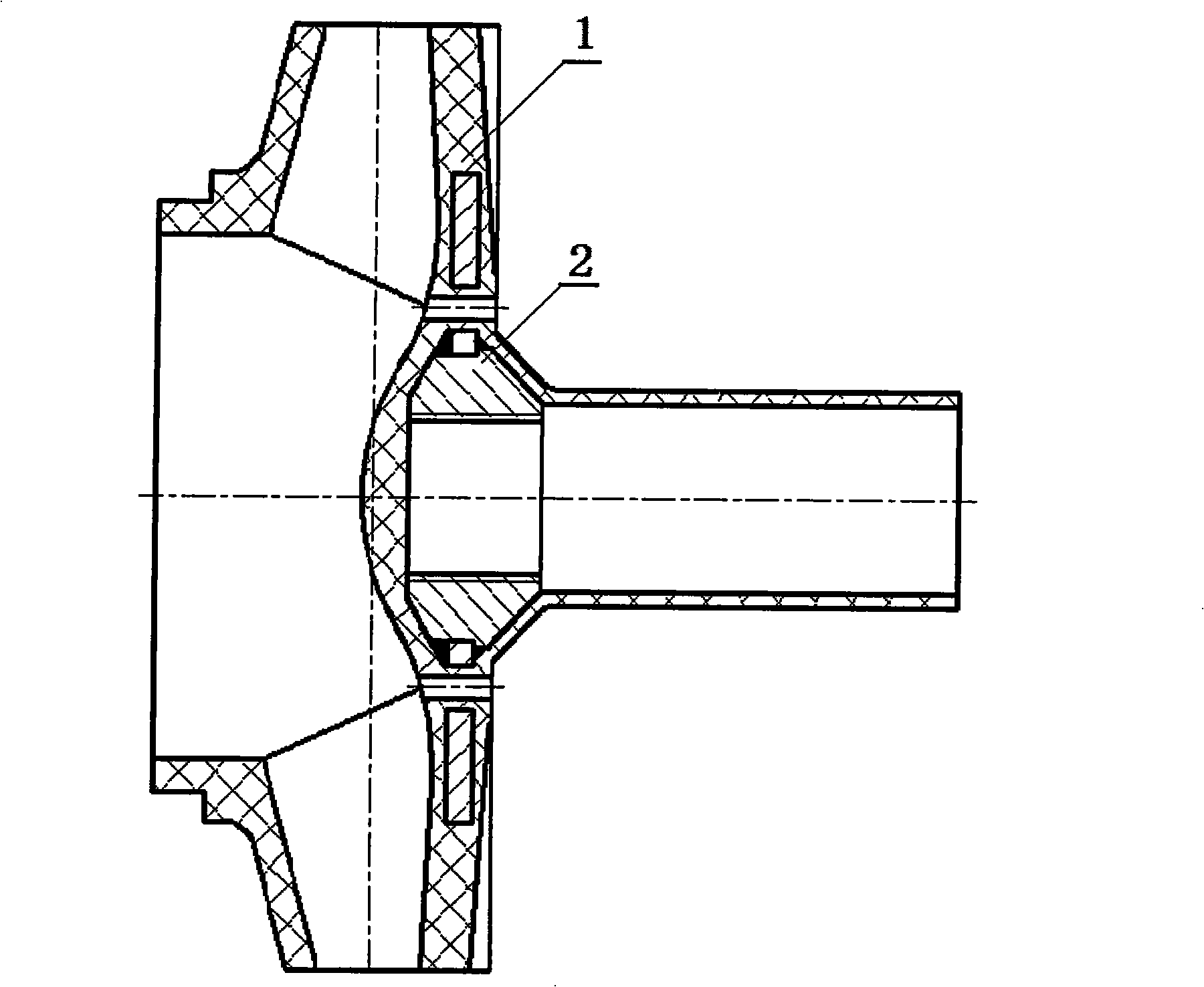
[0013] from figure 1 It can be seen that a corrosion-resistant chemical process pump impeller is characterized in that: the impeller 1 is made of ultra-high molecular weight polyperfluoroethylene propylene sintered and molded, and the impeller contains a metal bracket 2 inside.

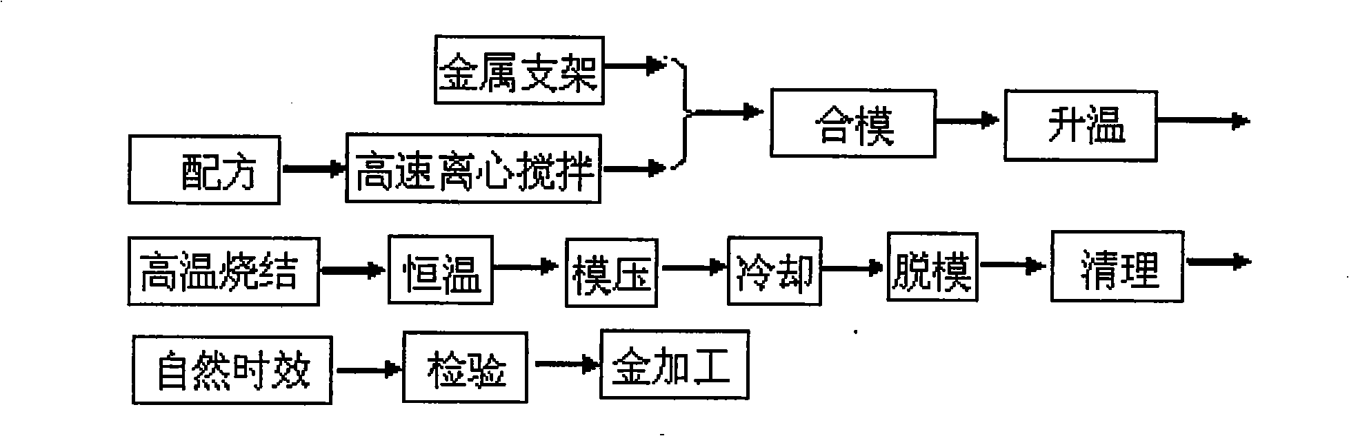
[0014] from figure 2 It can be seen that the processing technology of the impeller is as follows:

[0015] Firstly, the machined metal support 1 and the ultra-high molecular weight polyperfluoroethylene propylene after high-speed centrifugal stirring are injected into the mold to raise the temperature;

[0016] Sintering at a temperature of 370-390°C for 4.5-5.5 hours, then constant temperature at a temperature of 370-380°C for 2.5-3.5 hours and then molding under a pressure of 8-12MPa for 80-120 minutes;

[0017] The molded impeller 2 is demoulded after cooling, put in the natural environment for 110-130 hours, then carries out gold processing, and finally inspects and puts it into storage.


PUM


Abstract

The invention relates to a pump, in particular to an impeller used for the corrosion-resistant chemical process pump and applied in the fields the chemical engineering, the petroleum, the pharmacy, the acid cleaning, etc. The impeller is made from the ultra high molecular weight fluorinated ethylene propylene by die pressing under the pressure of 8 to 12 MPa after being sintered under the temperature of 370 to 390 DEG C, and a metal bracket is arranged inside the impeller. The impeller has the advantages that a corrosion-resistant and anti-leak shaft sleeve and the rear part of the impeller are formed into a connecting body, not only the shaft sleeve originally arranged is replaced, but also the seal leakage point is reduced; the appearance is beautiful, the installation is quick and convenient, the corrosion-resistant and temperature-resistant performances are long, the impeller is never aged, the high maintenance frequency and the high maintenance cost due to the vulnerable shaft sleeve is reduced, and the problem of reduction of the service life of the pump due to the corrosivity of the chemical mediator of the user is fundamentally solved.

Description

[0001] Field of the invention: The present invention relates to a pump, in particular to an impeller and its processing technology used in corrosion-resistant chemical process pumps used in the fields of chemical industry, petroleum, pharmacy and pickling. Background technique: [0002] Existing chemical process pumps, both metal and non-metal, are required to be anti-corrosion, and leakage is not allowed. Once leakage, the service life of the equipment will be reduced, or even scrapped. In the current structure of the pump, the connection between the impeller and the pump shaft is a key connection, and the impeller and the shaft sleeve are compressed by the shaft nut. This structure will inevitably form three sealing leakage points, and there are many leakage points, although the service life is not long. In the later period, foreign technology was introduced, and the improved connection between the pump shaft thread and the impeller was reduced to a seal leakage point. This s...

Claims


Application Information

Patent Timeline
Patent Type & Authority Applications(China)
IPC IPC(8): F04D29/20B29C70/70B29K27/12B29L31/08
Inventor 刘金坤
Owner 刘金坤
Why Eureka
Try Eureka