
System for modulating working frequency of switch power source converter

A technology of power converter and operating frequency, which is applied in the direction of control/regulation system, adjustment of electric variable, output power conversion device, etc., and can solve problems such as difficult to meet, large switching loss of converter, etc.

Inactive Publication Date: 2008-12-31
TIANYU INFORMATION TECH SHANGHAI
View PDF0 Cites 37 Cited by
  • Summary
  • Abstract
  • Description
  • Claims
  • Application Information

AI Technical Summary

Problems solved by technology

When the load is small or there is no load, since the switching frequency is fixed, the switching loss of the converter is always large, and it is difficult to meet the requirements of various energy-saving standards

Method used

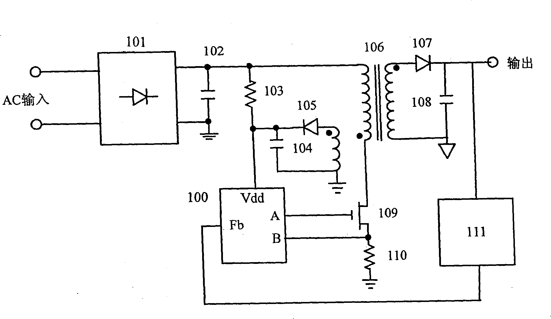
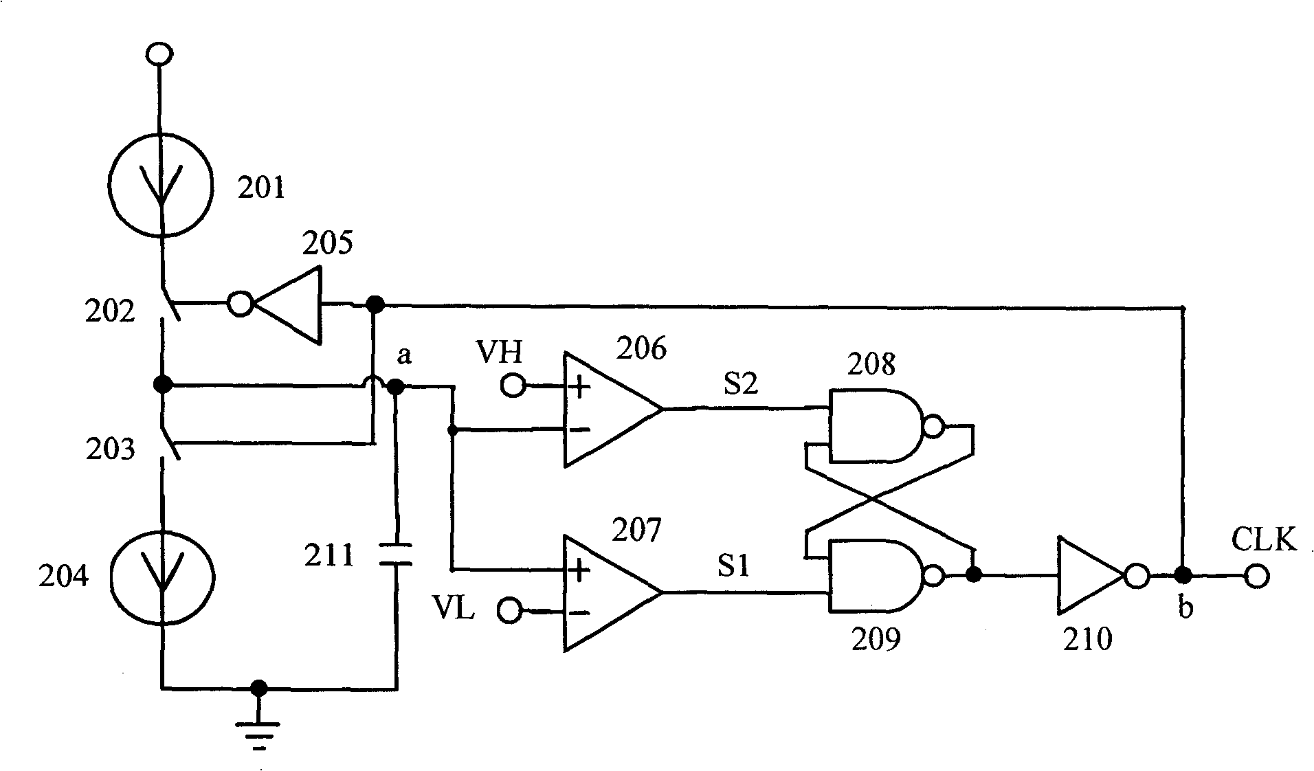
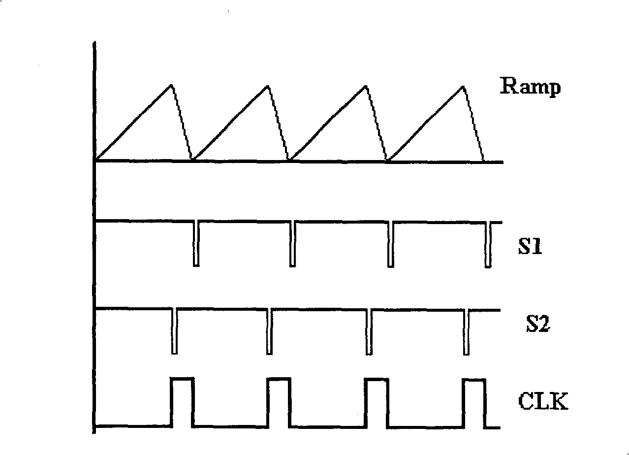

Image

  • System for modulating working frequency of switch power source converter
  • System for modulating working frequency of switch power source converter
  • System for modulating working frequency of switch power source converter

Examples


Embodiment Construction

[0019] FIG. 4 is a specific embodiment of the system for modulating the operating frequency of the switching power converter of the present invention. The FB signal in the figure is the feedback signal obtained after output sampling and loop compensation. After the signal passes through the voltage displacement and amplification circuit 301, it is sent all the way to the PWM comparator 303 and the current sampling voltage CS to compare and control the current flowing through the primary of the transformer. The other path is sent to the input end of one of the comparators in the oscillator 302, the oscillator 302 is provided with a charging and discharging circuit, a comparator array 307 and a waveform synthesis control circuit 308 to output a square wave signal CLK to the CLK end of the D flip-flop 304, The reset terminal R of the flip-flop 304 is connected to the output of the PWM comparator 303 , and the output terminal Q of the flip-flop is sent to the driver stage 305 to dr...


PUM


Abstract

The invention discloses a system for modulating the work frequency of a switch power converter. The system comprises an oscillator for receiving an input signal which represents the load situation of a switch power; the oscillator at least generates one first output signal, one cycle of which consists of three parts, namely a first time period, a second time period and a third time period; the first output signal boosts up during the first time period and the second time period, but falls during the third time period; wherein, the length of the second time period changes between zero and a maximum value preset along with the change of the input signal and the length of the input signal and the length of the second time period are inversely proportional. The second time period is modulated by a feedback signal so as to cause the work frequency of the switch power converter to be reduced when the switch power is under the conditions of light load and zero load, thus reducing power loss. The system of the invention can be widely applied to the switch power modulated by PWM.

Description

technical field [0001] The present invention relates to a system for modulating the operating frequency of a switching power converter, in particular to a switching power converter controlled by PWM (pulse width modulation). Background technique [0002] Electronic devices operate with electricity, and switching power supplies are widely used in current power electronic devices due to their high efficiency and small size. Although the traditional switching power supply provides high efficiency at full load, there is still a lot of power wasted at light load and no load, and now with many new energy-saving standards (Blue Angel, Energy Star, etc.) Promulgated and implemented, the traditional UC384X series controllers can no longer meet these standards. For this reason, various manufacturers have introduced various new solutions, and this invention is also proposed for this problem. [0003] Switching power supply losses include three types: (1) conduction loss: the loss caus...

Claims


Application Information

Patent Timeline
IPC IPC(8): H02M3/28H02M3/335
Inventor 康长胜胡旅顺张杰
Owner TIANYU INFORMATION TECH SHANGHAI
Learn More