Capillary pipe optical fibre and standard optical fibre connecting method

A technology of standard optical fiber and connection method, which is applied in the direction of cladding optical fiber, optical waveguide, optical waveguide coupling, etc., can solve the problems of different proportions of optical fiber cross-sectional area, different geometric shapes of optical waveguides, etc., and achieve easy production and light wave conversion. high efficiency effect

Inactive Publication Date: 2009-01-07
HARBIN ENG UNIV
View PDF5 Cites 23 Cited by
  • Summary
  • Abstract
  • Description
  • Claims
  • Application Information

AI Technical Summary

Problems solved by technology

For the new type of hollow capillary fiber whose core is a ring waveguide structure, the optical fiber to be connected has two main differences: (1) the area ratio of the fiber cross-section is different; (2) the geometric shape of the optical waveguide is different. , so there are many difficulties in the connection process

Method used


Image

  • Capillary pipe optical fibre and standard optical fibre connecting method
  • Capillary pipe optical fibre and standard optical fibre connecting method
  • Capillary pipe optical fibre and standard optical fibre connecting method

Examples


Embodiment ( 1

[0038] The present invention is realized like this in making implementation process, comprises the following several steps:

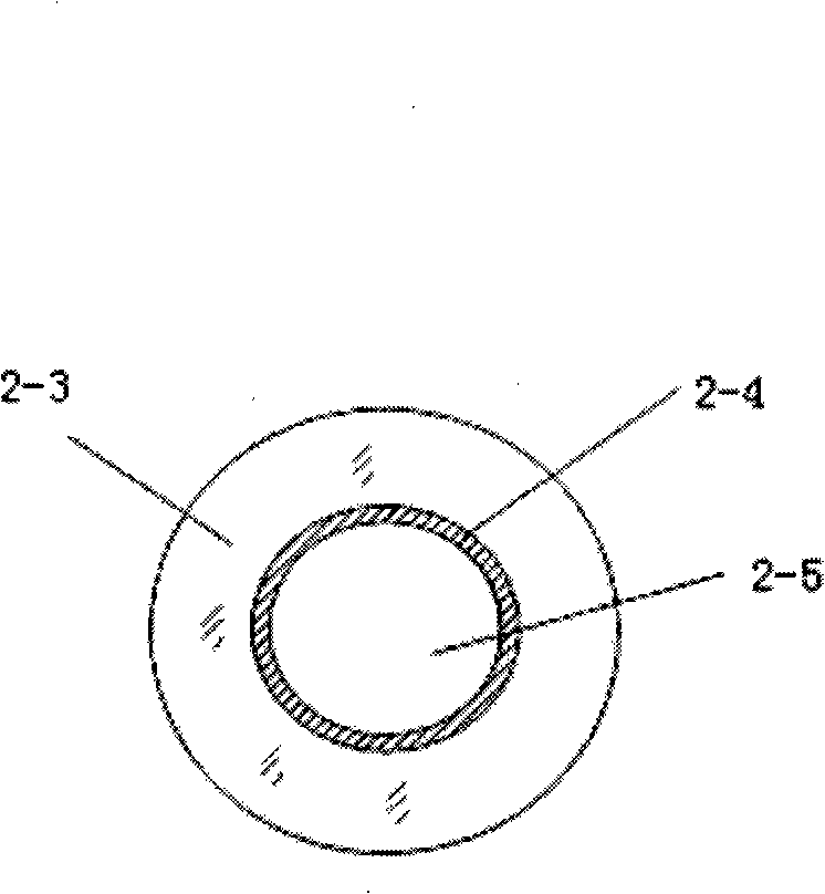
[0039] 1. If Figure 2-a For the hollow capillary optical fiber shown, peel off the coating layer at one end, and then clean it. During the cleaning process, prevent liquid from entering the hollow cavity of the capillary optical fiber;

[0040] 2. Carefully cut out the flat capillary fiber end face;

[0041] 3. Prepare the fiber end of the standard solid single-core fiber to be connected according to the same steps above;

[0042] 4. Put the prepared section of quartz protective tube on one end of standard single-core optical fiber or capillary optical fiber;

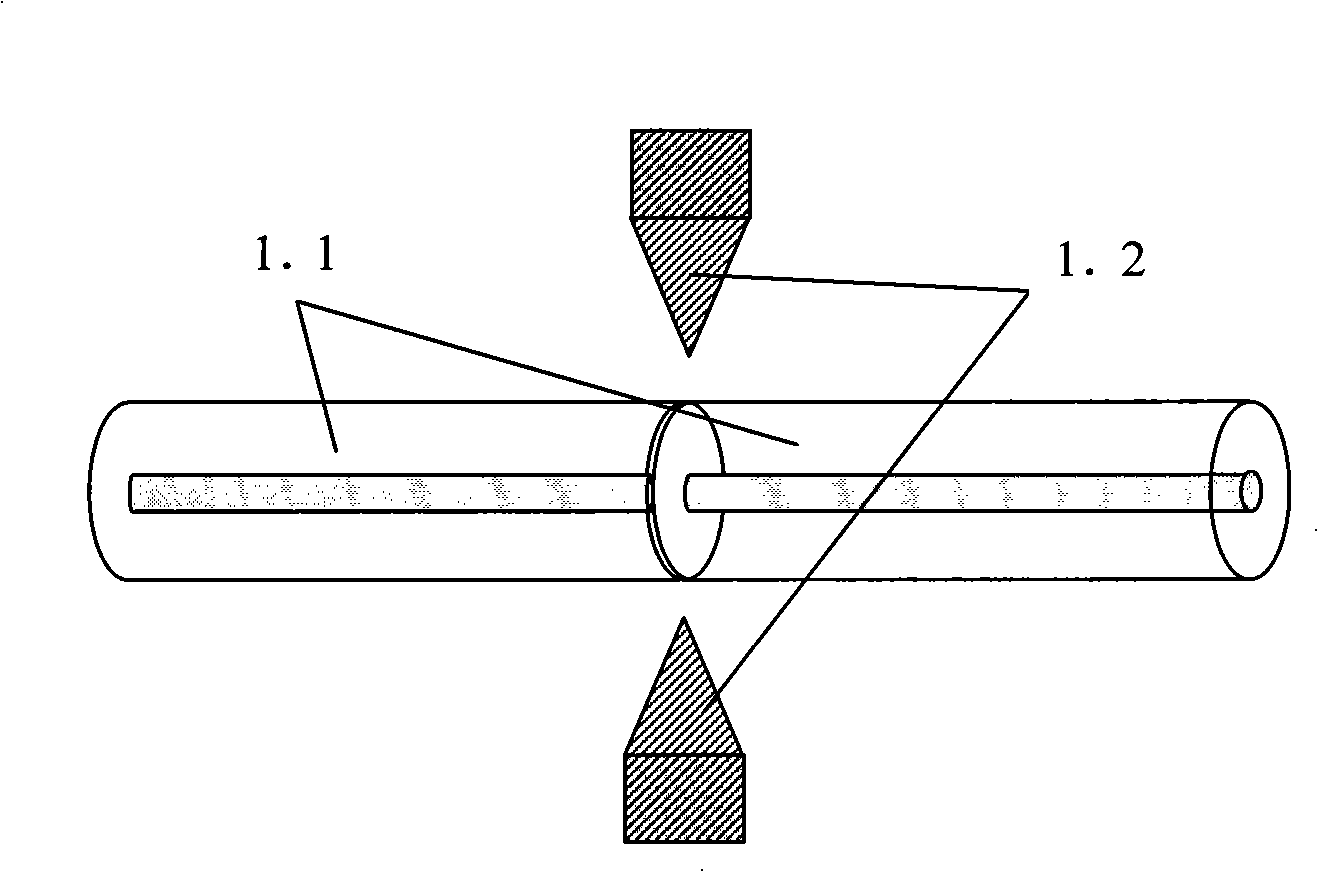
[0043] 5. Butt and weld the prepared two optical fiber ends in the optical fiber fusion splicer, such as figure 1 shown;

[0044] 6. When implementing fused tapering, since the diameters of the two optical fibers used are the same, both are 125 microns. The softening point of the hollow cap...

Embodiment ( 2

[0048] The second embodiment of the present invention is realized in the process of making and implementing, including the following steps:

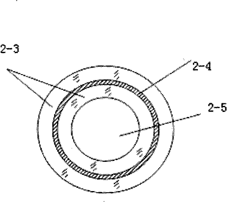
[0049] 1. Take as Figure 2-b For the hollow capillary optical fiber shown, peel off the coating layer at one end, and then clean it. During the cleaning process, prevent liquid from entering the hollow cavity of the capillary optical fiber;

[0050] 2. Carefully cut out the flat capillary fiber end face;

[0051] 3. Prepare the fiber end of the standard solid single-core fiber to be connected according to the same steps above;

[0052] 4. Put the prepared section of quartz protective tube on one end of standard single-core optical fiber or capillary optical fiber;

[0053] 5. Butt and weld the prepared two optical fiber ends in the optical fiber fusion splicer, such as figure 1 shown;

[0054] 6. In the actual fusion tapering, since the diameters of the two optical fibers used are the same, both are 125 microns. The softening point...


PUM


Abstract

The invention provides a connecting method for a capillary optical fiber and a standard optical fiber, which comprises the following steps: stripping and washing the coating layer at one end of the capillary optical fiber, the standard optical fiber or a multimode optical fiber respectively and cutting a tidy optical fiber head face; fusing and welding through an optical fiber welder; preheating for Delta t seconds at the position where a welding point leans a distance of delta from the standard optical fiber or the multimode optical fiber (the value range of Delta is 0.1 - 3.5mm, the value range of Delta t is 3 - 12 seconds); implementing fused biconical taper to form a tapered light energy distribution area; carrying out optical power monitoring to one end of the capillary optical fiber in the process of fused biconical taper so as to form a tapered coupling area; sheathing a quartz protection sleeve outside of the tapered coupling area and sealing the both ends of the quartz protection sleeve with the standard optical fiber and the capillary optical fiber. The method solves the connection problem of the standard optical fiber and the hollow capillary optical fibers with the same diameter but different cross-sectional area ratio, and has the advantages of easy manufacturing and high light-wave conversion efficiency.

Description

(1) Technical field [0001] The invention relates to an optical fiber connection method, in particular to a connection method between a capillary optical fiber and a standard single-mode optical fiber or a multi-mode optical fiber. (2) Background technology [0002] Optical fiber connection technology is the most basic expertise in the field of optical fiber applications. Optical fiber splicing refers to combining the end faces of two optical fibers together. The basic requirement for the connection is to maximize the coupling and transition of light energy from the input fiber to the receiving fiber. In addition to requiring small connection loss and large return loss, the optical fiber connection technology also requires stable performance and sufficient mechanical strength when the ambient temperature changes. Therefore, precise mechanical and optical design and processing assembly are required to ensure high-precision matching of the two fiber ends. [0003] There are ...

Claims


Application Information

Patent Timeline
Patent Type & Authority Applications(China)
IPC IPC(8): G02B6/255G02B6/24G02B6/02
Inventor 苑立波杨军朱晓亮
Owner HARBIN ENG UNIV
Why Eureka
Try Eureka