
Switching power supply apparatus

A switching power supply and switching element technology, applied in the output power conversion device, electrical components, adjusting electrical variables and other directions, can solve the problem of reducing the sound effect in the audible frequency domain, and achieve the purpose of reducing power consumption, stabilizing power supply, simplifying The effect of the control circuit

Inactive Publication Date: 2009-01-07
FUJI ELECTRIC SYST CO LTD
View PDF4 Cites 11 Cited by
  • Summary
  • Abstract
  • Description
  • Claims
  • Application Information

AI Technical Summary

Problems solved by technology

However, when the switching element 2 stops oscillating, the state in which current flows through the insulating transformer 3 suddenly changes to a state in which no current flows, so there is a problem that the effect of reducing sound in the audible frequency range is reduced.

Method used


Image

  • Switching power supply apparatus
  • Switching power supply apparatus
  • Switching power supply apparatus

Examples


Embodiment Construction

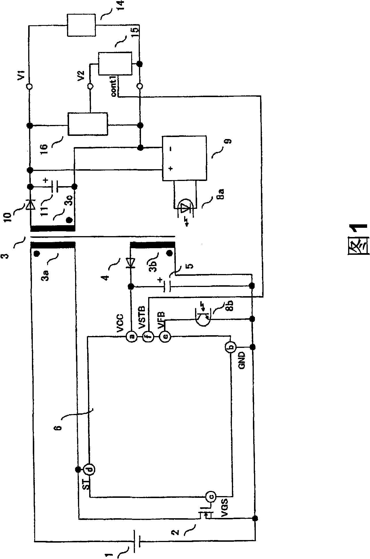
[0044] FIG. 1 shows a circuit configuration of a switching power supply device according to an embodiment of the present invention based on the first aspect. As shown in the figure, it is characterized in that the switching signal cont1 from the microcomputer 15 is introduced into the control circuit 6, and a voltage stabilizing unit 16 for stabilizing the input voltage of the microcomputer 15 is provided, and other points are the same as those in Fig. 10 and Fig. 12 is the same. Here, as the voltage stabilizing means 16 , for example, well-known means such as a chopper control power supply and a series regulator power supply can be used, and thus detailed description thereof will be omitted.

[0045] Further, the switching signal cont1 from the microcomputer 15 is insulated from the primary side of the transformer by a photocoupler or the like. The same applies to the following embodiments.

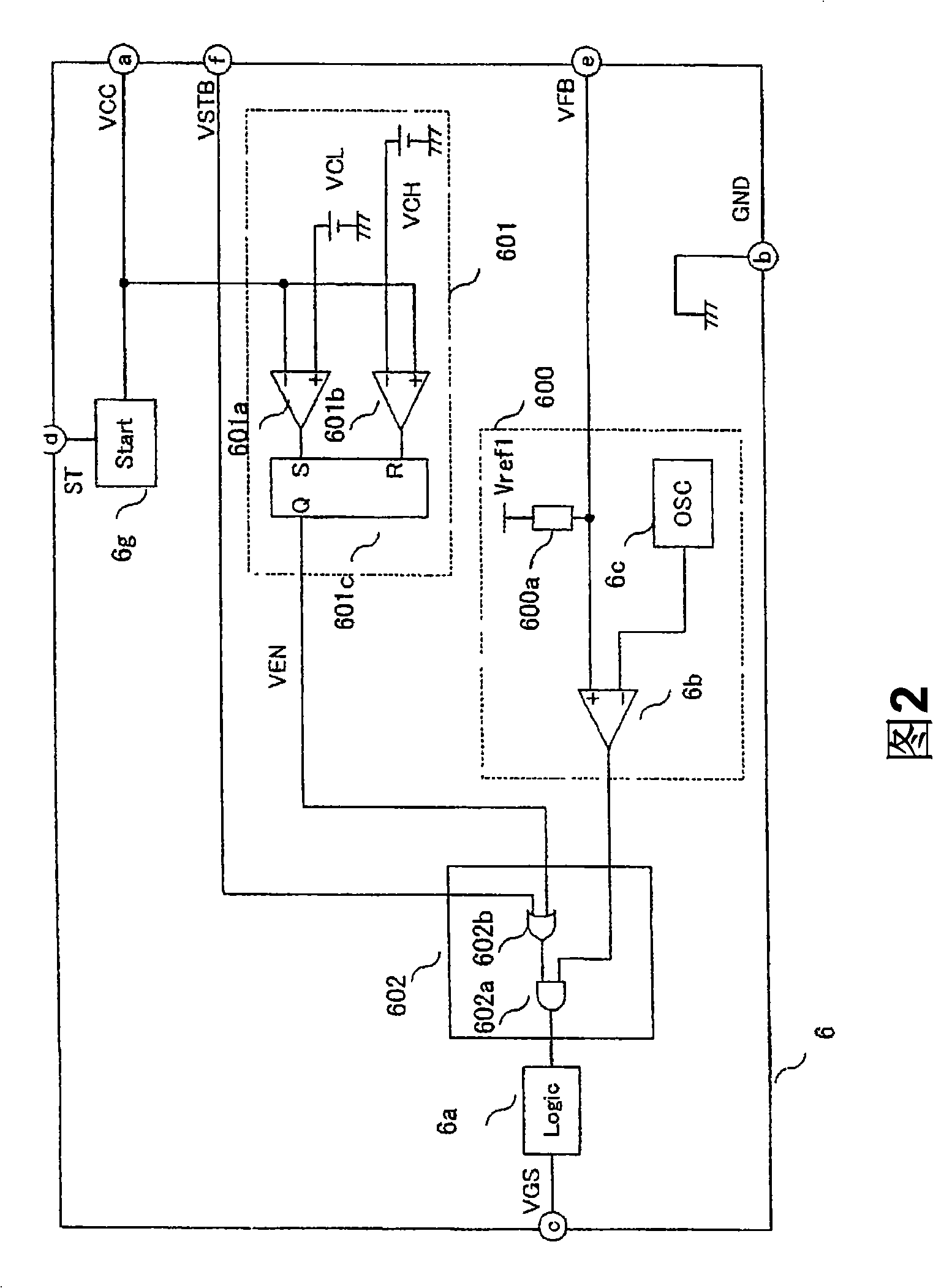
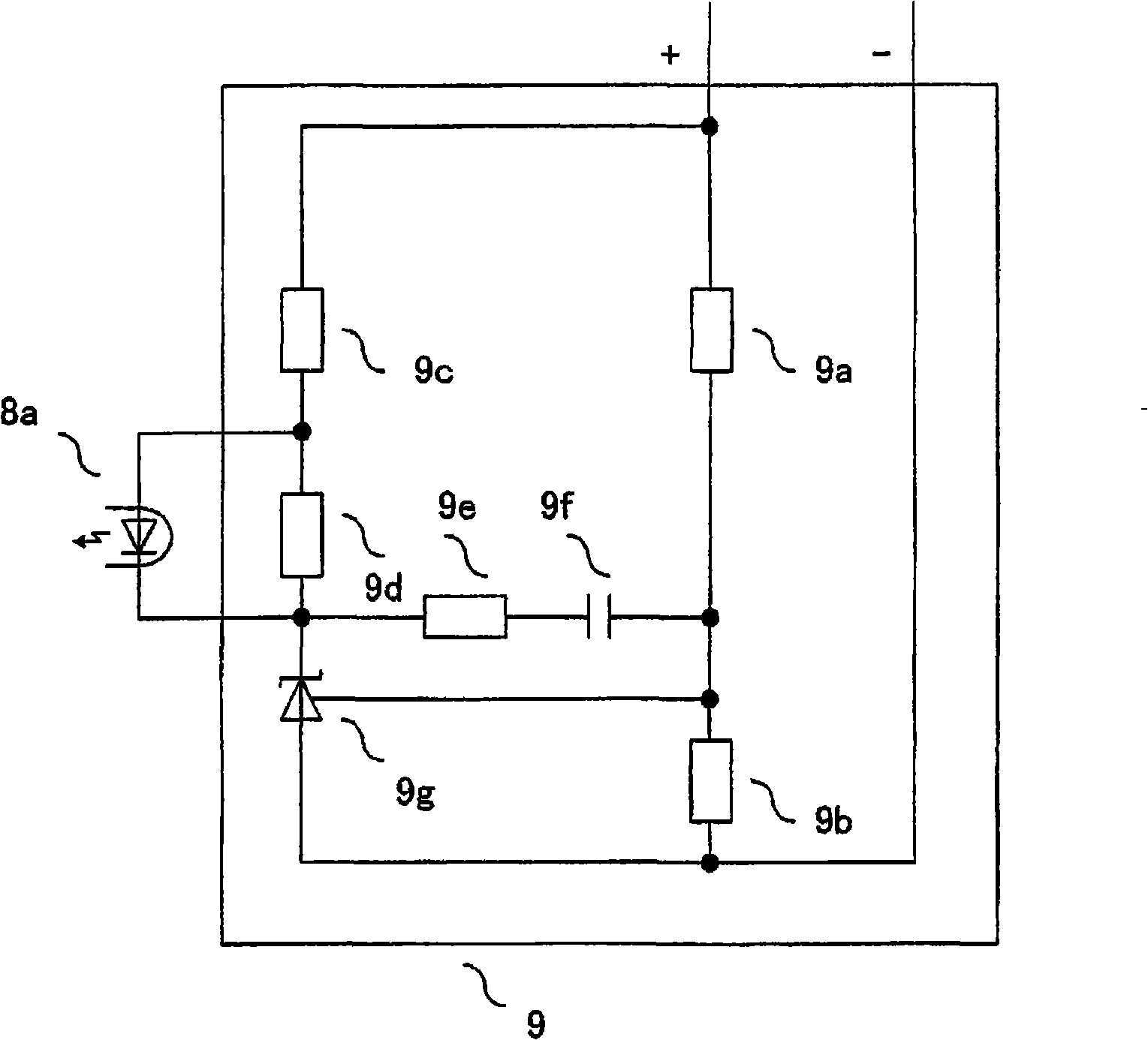
[0046] 2 is a circuit diagram showing a specific example of a control circuit, whi...


PUM


Abstract

The invention relates to a switching power supply apparatus which is able to restrain the increase of electrostatic capacitance of smoothing capacitor connected with control circuit of the switching power supply apparatus, and is able to use the small smoothing capacitor with low cost, and is able to reduce the power consumption and is able to reduce the sound of audible frequency domain generated by the transformer. The switching power supply apparatus includes a DC power supply (1), an isolation transformer (3) having primary, secondary and tertiary windings, and a switching element (2), and in which, by turning the switching element (2) on and off, the high-frequency voltage appearing in the secondary windings of the isolation transformer is rectified to obtain a DC output, power consumption can be decreased during standby (in burst mode) in particular by means of a control circuit (6) which controls the turn-on and turn-off of the element and similar.

Description

technical field [0001] The invention relates to a switching power supply device which obtains an isolated DC output from a DC power supply, in particular to a switching power supply device capable of reducing power consumption during standby. Background technique [0002] In recent years, as a countermeasure against global warming, the reduction of power consumption of electric equipment has been progressing. In particular, in order to reduce the power consumed when the power equipment is not in use, many inventions have been proposed on switching power supply devices having a standby mode for supplying only the minimum necessary power to the device. (Refer to Patent Documents 1 and 2) [0003] An example of a switching power supply device having the same configuration as the devices described in Patent Documents 1 and 2 is shown in FIG. 10 . refer to Figure 11 Explain its action. [0004] In the standby mode, the feedback signal VFB of the DC output voltage is compared ...

Claims


Application Information

Patent Timeline
Patent Type & Authority Applications(China)
IPC IPC(8): H02M3/28H02M3/335
CPCY02B70/16H02M3/33515H02M2001/0032H02M3/33523Y02B70/10H02M1/0032
Inventor 西川幸广
Owner FUJI ELECTRIC SYST CO LTD
Learn More