Magnetic resonance scanner with a longitudinal magnetic field gradient system

A longitudinal magnetic field and scanner technology, applied in the direction of instruments, measuring magnetic variables, measuring devices, etc., can solve the problems of complex design of quench detection and protection circuits, field errors, etc., and achieve reduced pressure, small magnet diameter, and simplified design Effect

Inactive Publication Date: 2009-01-07
KONINKLIJKE PHILIPS ELECTRONICS NV
View PDF0 Cites 4 Cited by
  • Summary
  • Abstract
  • Description
  • Claims
  • Application Information

AI Technical Summary

Problems solved by technology

In addition, medium currents caused by induced voltages can cause field errors like eddy currents
Furthermore, the induced voltage complicates the design of quench detection and protection circuits for the main magnet

Method used


Image

  • Magnetic resonance scanner with a longitudinal magnetic field gradient system
  • Magnetic resonance scanner with a longitudinal magnetic field gradient system
  • Magnetic resonance scanner with a longitudinal magnetic field gradient system

Examples


Embodiment Construction

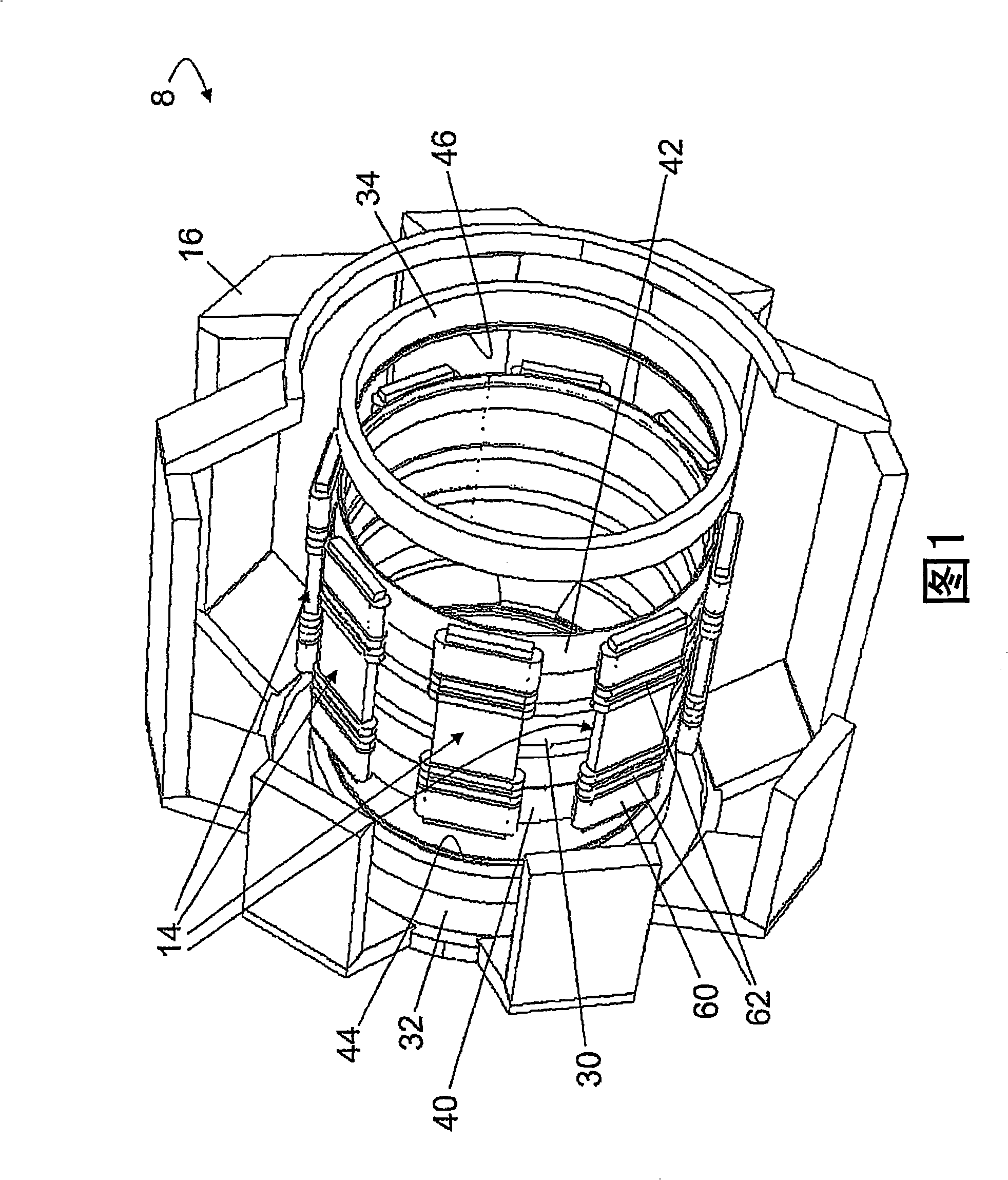
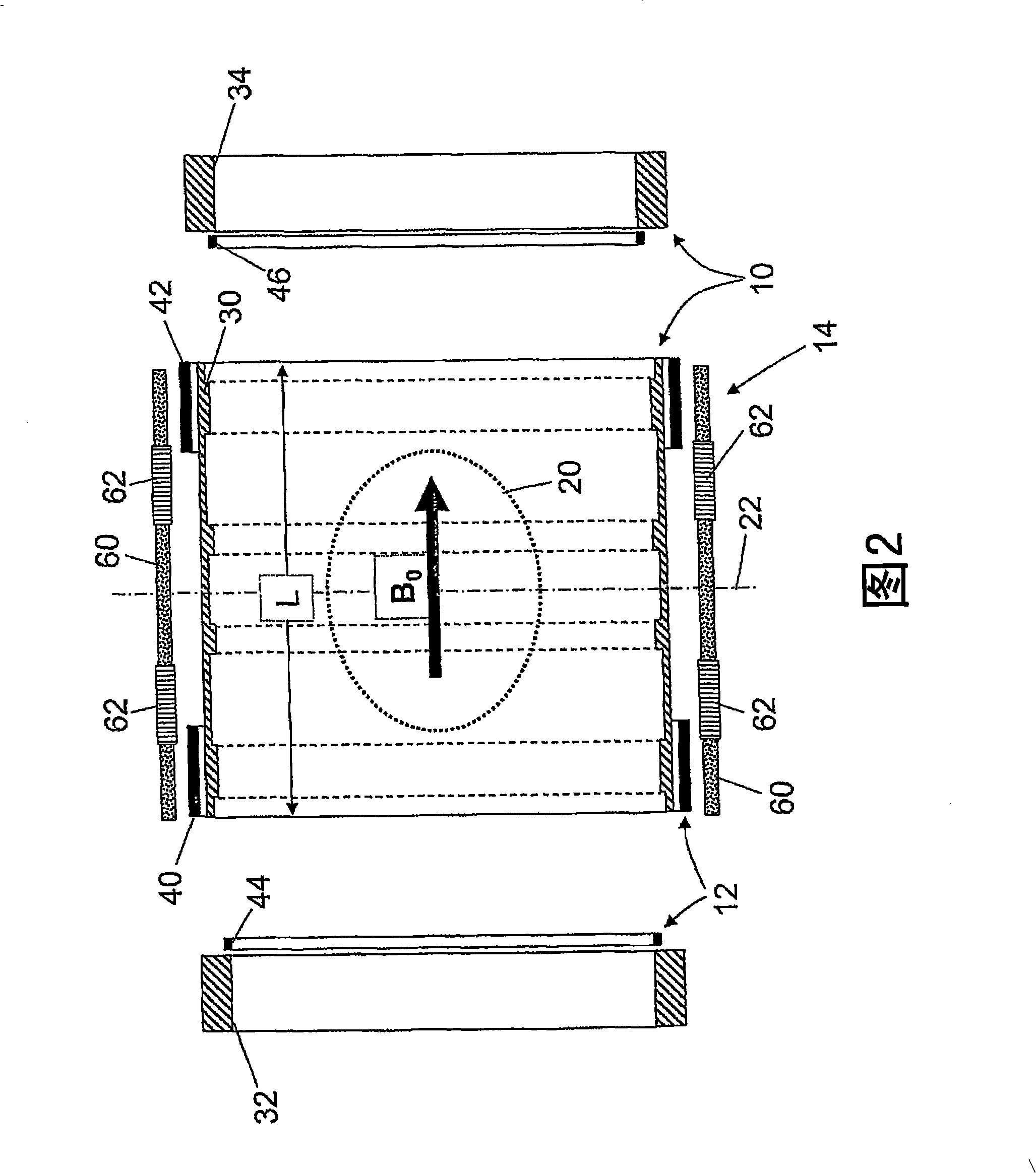
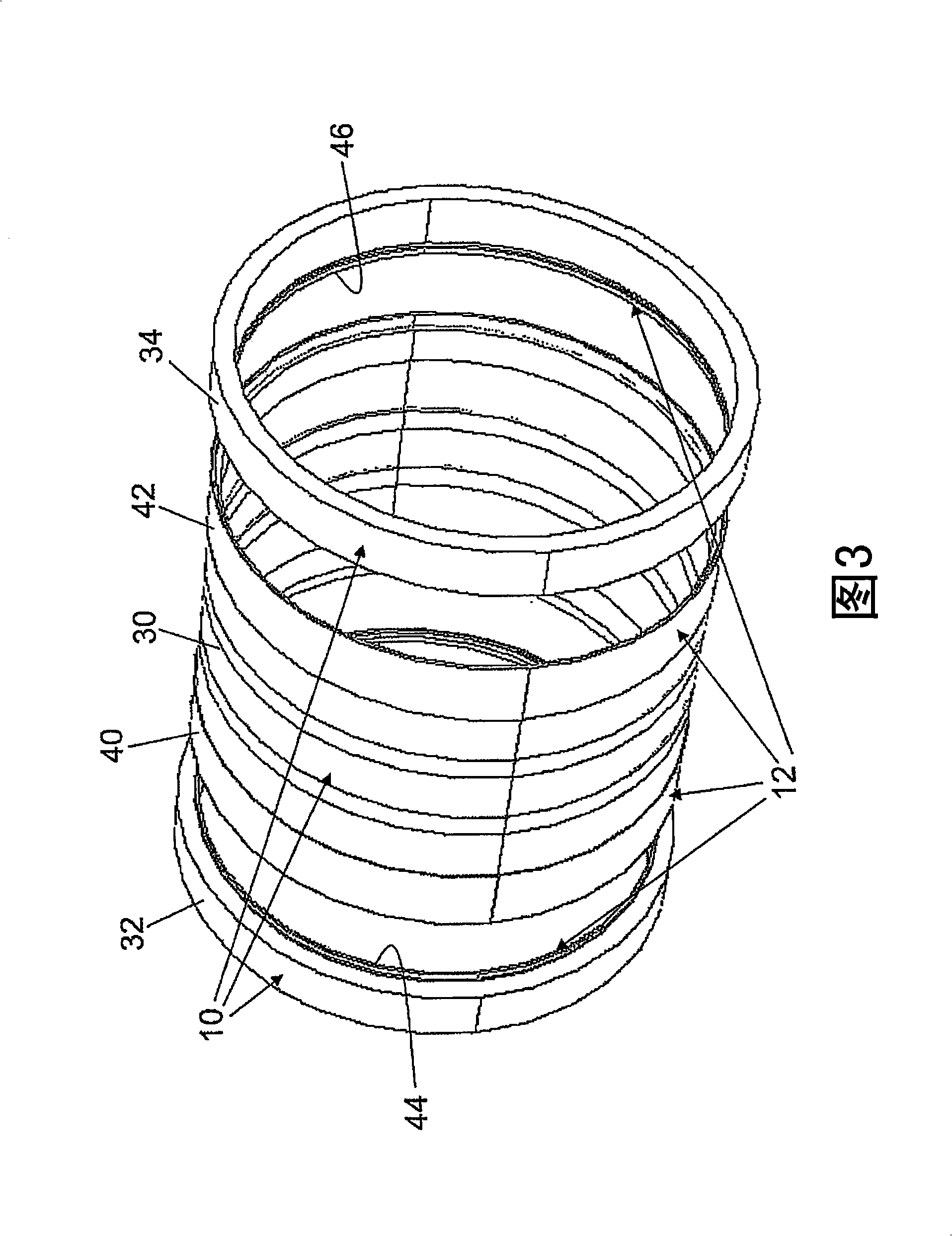
[0022] 1-5, a magnetic resonance scanner 8 is suitable for performing magnetic resonance imaging, magnetic resonance spectroscopy, etc., and it includes a main magnet system 10 (the system marked in FIGS. 2-5), a longitudinal magnetic field gradient system 12 (in the figure 2-5), the transverse magnetic field gradient system 14 (the system marked in FIGS. 1-2 ), and the ferroflux side yoke 16 (shown in FIG. internal scanner parts).

[0023] The main magnet system 10 is wound for generating a longitudinally oriented main magnetic field B at least in the scanning zone 20 0 (Schematically shown in Figures 2 and 5). The main magnet system 10 is longitudinally symmetrical about the central scanner plane 22 . The main magnet system 10 includes a layer-by-layer wound central magnet winding region 30 disposed between outer magnet winding regions 32 , 34 . The outer magnet winding areas 32 , 34 are arranged symmetrically with respect to the central scanner plane 22 . The central ma...


PUM


Abstract

In a magnetic resonance scanner, a main magnet system (10) is wound to generate a longitudinally directed main magnetic field (B0) at least in a scanning region (20). The main magnet system includes a central magnet winding region (30) wound layer-by-layer disposed between outer magnet winding regions (32, 34). A longitudinal magnetic field gradient system (12, 12') includes a central gradient winding region (40, 40', 42, 42') wound to generate a main longitudinally directed magnetic field gradient disposed between outer gradient winding regions (44, 46) wound to generate a compensatory longitudinally directed magnetic field gradient having opposite polarity from the main longitudinally directed magnetic field gradient. The outer gradient winding regions are arranged to substantially null mutual inductance between the outer magnet winding regions (32, 34) and the longitudinal magnetic field gradient system (12, 12').

Description

technical field [0001] The following relates to the field of magnetic resonance. It has particular applicability to magnetic resonance imaging and is described with specific cited applications. More generally, however, it is also applicable to magnetic resonance imaging, magnetic resonance mapping, magnetic resonance spectroscopy, etc. Background technique [0002] In order to reduce the size and cost of the magnetic resonance scanner, it is advantageous to place the windings of the gradient coils close to the windings of the main magnet, usually with a slightly smaller radius than the main magnet windings. However, this arrangement is difficult to include shielding for the gradient coils. [0003] In the absence of shielding, it is generally found that there is considerable electromagnetic coupling between the longitudinal or z-gradient coils and the main magnet of the aperture scanner. For example, the inventors have estimated that the longitudinal magnetic field gradie...

Claims


Application Information

Patent Timeline
Patent Type & Authority Applications(China)
IPC IPC(8): G01R33/385
CPCG01R33/3856G01R33/385
Inventor J·A·奥弗韦格
Owner KONINKLIJKE PHILIPS ELECTRONICS NV
Why Eureka
Try Eureka