Accurate hob cutter with inserted tooth
A hob, insert technology, applied in the direction of gear teeth, components with teeth, gear teeth manufacturing devices, etc.
Inactive Publication Date: 2009-01-14
JILIN UNIV
View PDF3 Cites 8 Cited by
- Summary
- Abstract
- Description
- Claims
- Application Information
AI Technical Summary
Problems solved by technology
[0004] However, the series of fine hobs with the above-mentioned position-specific surface configurations are sometimes limited to selecting different blade cutting angles. For this reason, under the conditions of keeping the above-mentioned multiple hob configurations simple and easy to manufacture, further seek The fine hob with insert structure can adapt to more different types of cutting conditions
Method used
View moreImage
Smart ImageViewing Examples
Examples
Embodiment
[0067]
[0068] d
[0069] .
Login to View More PUM
 Abstract
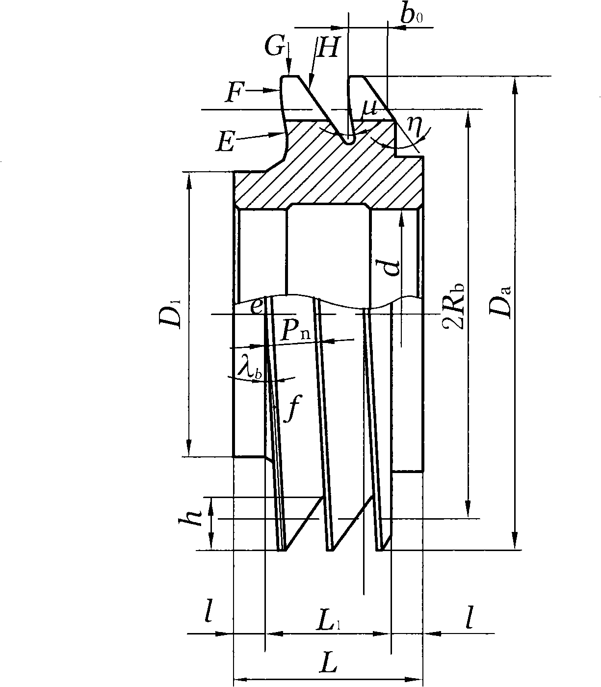
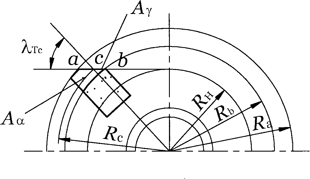
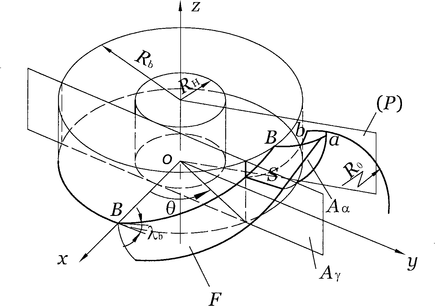
The invention discloses an inserted finishing hob which can overcome the problem of limited cutting angle caused by selecting the different cutting edges. A basic worm of the structure is provided with a spiral groove with headage i, lead p and groove depth h. Rb is the radius of the base cylinder of the basic worm. A line outside the base circle at the working side which is tangent to the base cylinder with the radius Rb and has the inclination angle Lambda b with the top surface of the base cylinder, is utilized as the generating line, and the generating line rolls along the base cylinder to form an involute helicoid, and the involute helicoid is the generating flank (F) of the hob of the basic worm configuration. Z gullets of the basic worm are respectively fixedly provided with a cutter tooth block which is uniformly positioned on the helical tooth of the basic worm. The front face of the hob Agamma is the plane and is tangent to the cylindrical surface of a mill knife with the radius RH. The intersection line of the generating flak of the basic worm (F) and the front face of the hob Agamma is the cutting edge of the hob (S), and the circle surface formed by the cutting edge of the hob (S) revolving around the axis oz is utilized as the back face of the hob Aalpha. The inserted finishing hob is more suitable for the finish machining of large modulus and heavy-duty gear.
Description
technical field [0001] The invention relates to a hob applied to the finishing of involute cylindrical gears, more specifically, it relates to an insert fine hob used for fine cutting the tooth surface of the gear. Background technique [0002] The applicant obtained the name "Gear Finishing Hob" in China, patent number 92105109.3, application date 1992.06.27, publication date 1994.01.12, publication number CN1080578 and the name "GEARFINISHING HOB" (gear fine hob) in the United States, Patent No. 5.338.134, application date 1993.06.25, publication date 1994.08.16, after the patent right of publication No. US005338134A, further technical development and improvement, in China also applied for the name "gear fine hob configuration method and its Configuration fine hob", application number 200710055491.X, application date 2007.04.06, publication date 2007.09.05, publication number CN101028660A invention patent. In the patent application, the basic worm screw that is conjugated...
Claims
Login to View More Application Information
Patent Timeline
 Patent Type & Authority Applications(China)
IPC IPC(8): B23F21/16
Inventor 彭福华呼咏
Owner JILIN UNIV
Features
- R&D
- Intellectual Property
- Life Sciences
- Materials
- Tech Scout
- Unparalleled Data Quality
- Higher Quality Content
- 60% Fewer Hallucinations
Learn More Browse by: Latest US Patents, China's latest patents, Technical Efficacy Thesaurus, Application Domain, Technology Topic, Popular Technical Reports.
© 2025 PatSnap. All rights reserved.Legal|Privacy policy|Modern Slavery Act Transparency Statement|Sitemap|About US| Contact US: help@patsnap.com


