Passive movement loading system of watercraft steering engine with varying load torque
A technology of passive loading and load moment, which is applied to ship components, ship construction, ship design, etc., can solve the problems of inability to simulate the force of the steering gear, the inability to adjust the loading moment in real time, and the large size of the loading system, so as to shorten the development time Period, compact structure, and the effect of ensuring personnel safety
- Summary
- Abstract
- Description
- Claims
- Application Information
AI Technical Summary
Problems solved by technology
Method used
Image

Examples
specific Embodiment approach 1
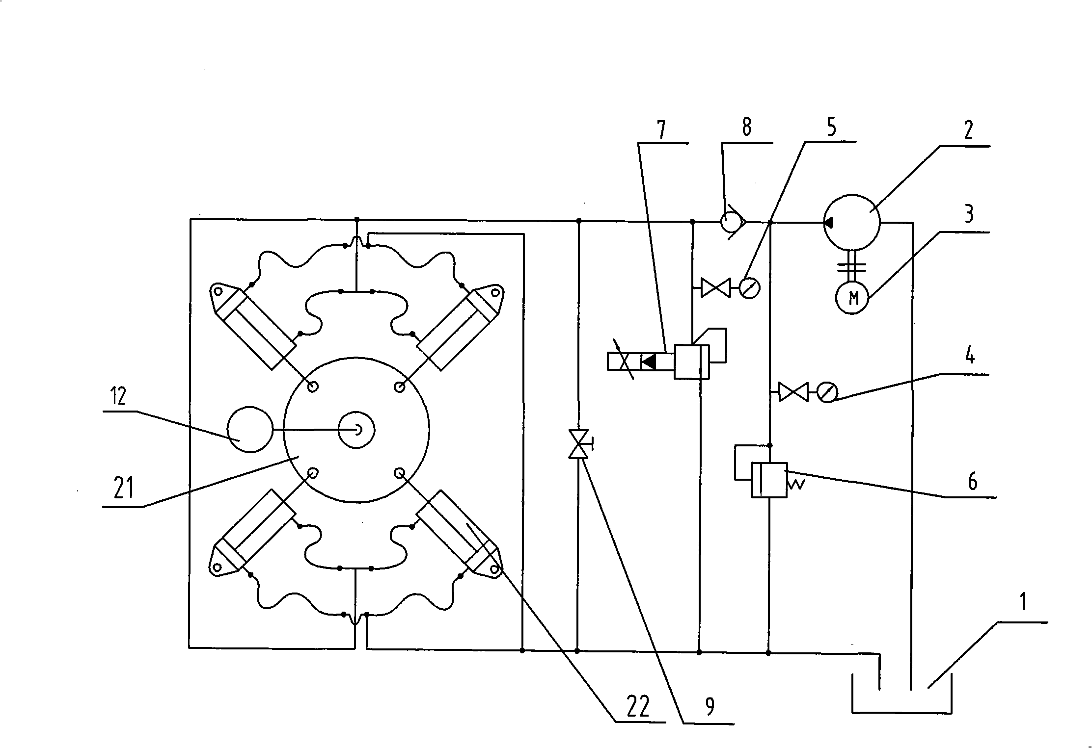
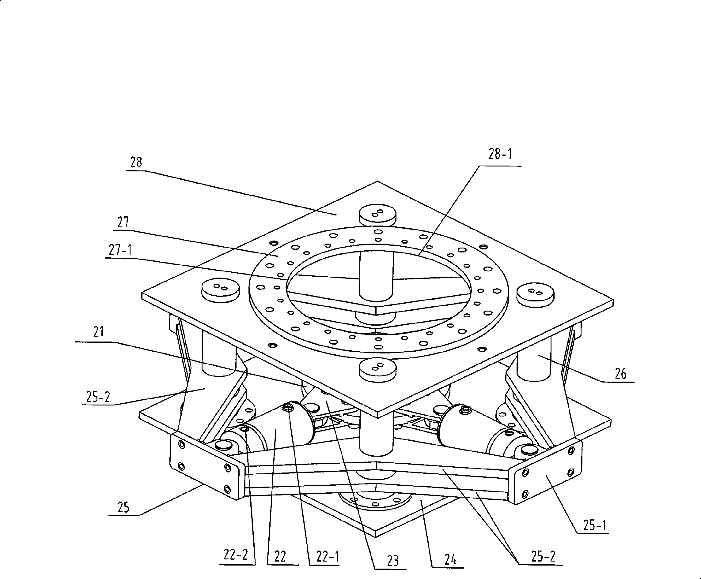
[0007] Specific implementation mode one: as figure 1 , figure 2 and image 3 As shown, the passive loading system of variable load moment ship steering gear in this embodiment is composed of a hydraulic system and a loading platform. The hydraulic system includes a fuel tank 1, an oil charging pump 2, an oil charging pump motor 3, a pressure sensor 5, and an oil charging pump Low-pressure relief valve 6, proportional relief valve 7 for loading, one-way valve 8 and stop valve 9; the loading platform includes base plate 24, support plate 28, four pillars 26, support frame 25, tiller handle 21, four A connector 23 and four loading cylinders 22, the four loading cylinders 22 are provided with cylinder oil inlets 22-1 on the side walls of the rod cavity, and the four loading cylinders 22 are provided with the rodless cavity side walls. There is an oil cylinder oil outlet 22-2; the output shaft of the oil charging pump motor 3 is connected to the oil charging pump 2, the oil tan...
specific Embodiment approach 2
[0009] Specific implementation mode two: as figure 2 and image 3 As shown, the support frame 25 in this embodiment is composed of four end plates 25-1 and eight cross braces 25-2, the four end plates 25-1 are vertically arranged, and each two cross braces The boards 25-2 are vertically facing and arranged horizontally, and the two ends of each two cross-bracing boards 25-2 are fixedly connected by the corresponding end boards 25-1 to form four frames. The supporting frame has the advantages of compact and simple structure, small footprint and the like. Other components and connections are the same as those in the first embodiment.
specific Embodiment approach 3
[0010] Specific implementation mode three: as figure 1 As shown, the hydraulic system in this embodiment further includes a pressure gauge 4 , and the pressure gauge 4 is installed on the oil circuit between the low-pressure relief valve 6 of the charge pump and the charge pump 2 . The pressure gauge 4 is used to measure the working pressure of the charge pump 2 . Other components and connections are the same as those in the first embodiment.
PUM
 Abstract
Description
Claims
Application Information
 - R&D
- Intellectual Property
- Life Sciences
- Materials
- Tech Scout
- Unparalleled Data Quality
- Higher Quality Content
- 60% Fewer Hallucinations
Browse by: Latest US Patents, China's latest patents, Technical Efficacy Thesaurus, Application Domain, Technology Topic, Popular Technical Reports.
© 2025 PatSnap. All rights reserved.Legal|Privacy policy|Modern Slavery Act Transparency Statement|Sitemap|About US| Contact US: help@patsnap.com