Coolant injection device and control method of rotary compressor

A technology of rotary compressor and compressor pump, applied in the direction of rotary piston type/swing piston type pump components, components of pumping devices for elastic fluids, mechanical equipment, etc. Reduce the efficiency of the machine system and other problems, and achieve the effect of preventing the reduction of efficiency, simple structure and easy change.

Inactive Publication Date: 2009-01-14
GUANGDONG MEIZHI COMPRESSOR
View PDF0 Cites 14 Cited by
  • Summary
  • Abstract
  • Description
  • Claims
  • Application Information

AI Technical Summary

Problems solved by technology

Moreover, with the rotation of the piston, the charging hole is continuously opened and closed, so the effective hole area is about 1/2 of the above-mentioned diameter, so this charging method cannot correspond to a system filled with a large amount of refrigerant
Moreover, the opening and closing of the filling hole depends on t

Method used


Image

  • Coolant injection device and control method of rotary compressor
  • Coolant injection device and control method of rotary compressor
  • Coolant injection device and control method of rotary compressor

Examples


no. 1 example

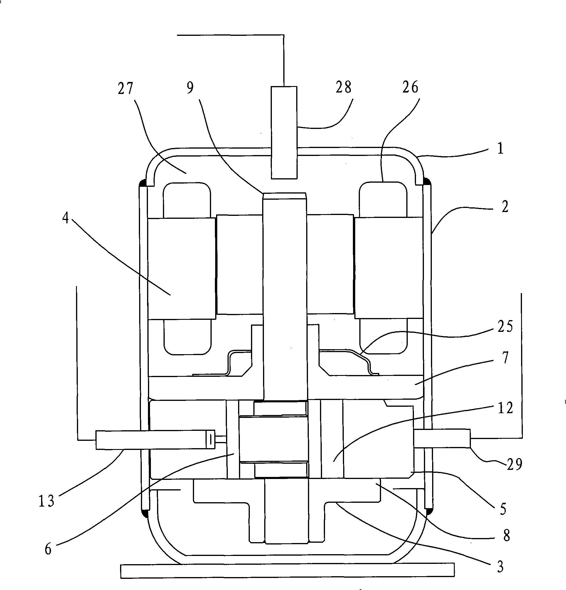
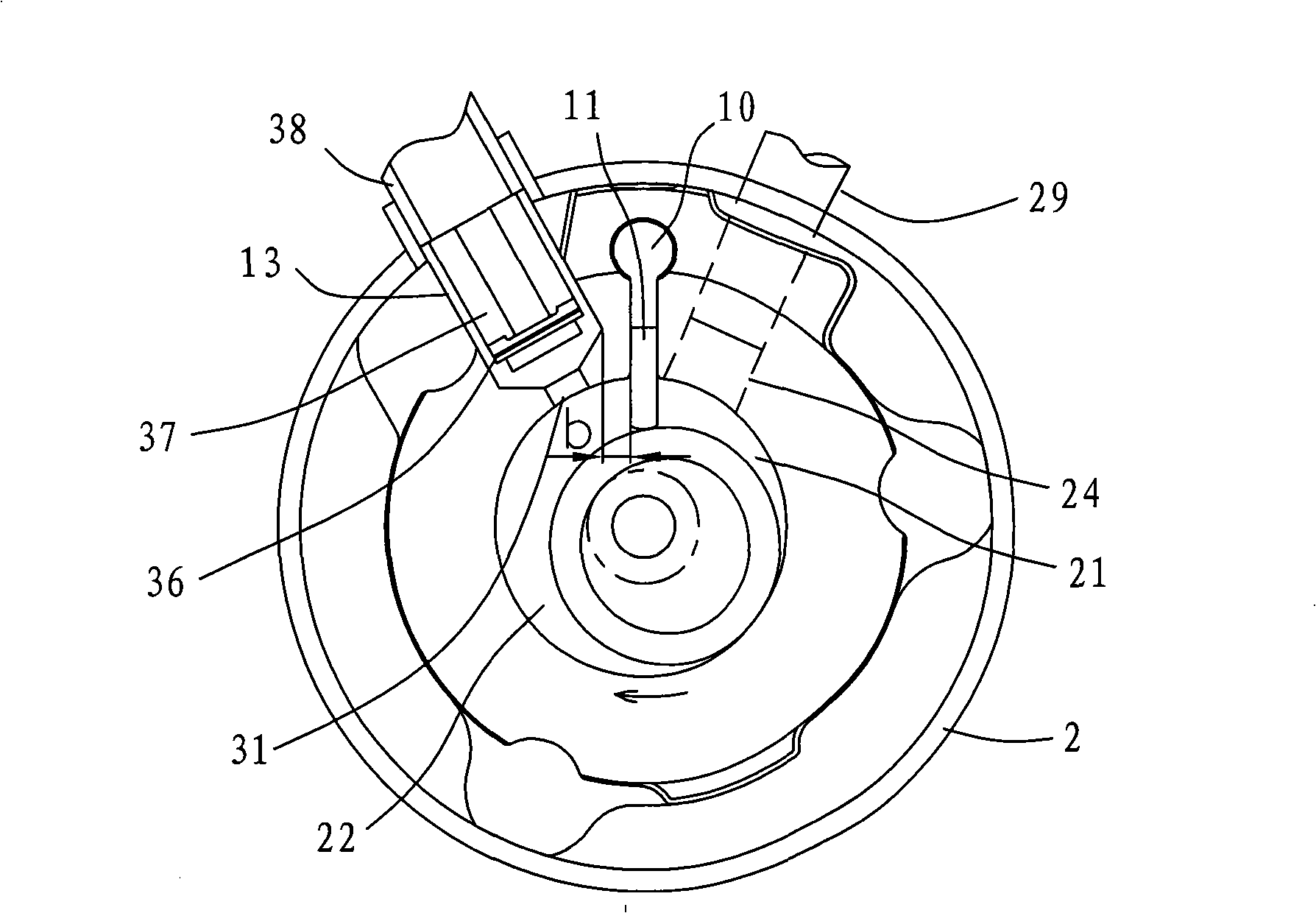
[0032] see figure 1 , figure 2 , a refrigerant charging device for a rotary compressor, including a motor 4 set in a sealed casing 2 and a compressor pump body 3 connected to the motor, the compressor pump body includes a cylinder 5, and the cylinders are respectively arranged on the upper and lower parts of the cylinder. The main bearing 7 and the auxiliary bearing 8, the crankshaft 9 connected with the motor, the cylinder compression chamber 12 that accommodates the freely rotatable piston 6 connected to the crankshaft, the slide plate 11 whose front end is crimped on the outer circle of the piston, and the storage slide Slider groove 10 for the sheet. The cylinder 5, the main bearing 7 or the auxiliary bearing 8 of the compressor pump body 3 are provided with a refrigerant charging device, which at least has a charging hole 31 perforated in the cylinder compression chamber 12 and a charging hole 31 which is opened as the pressure of the cylinder compression chamber change...

no. 2 example

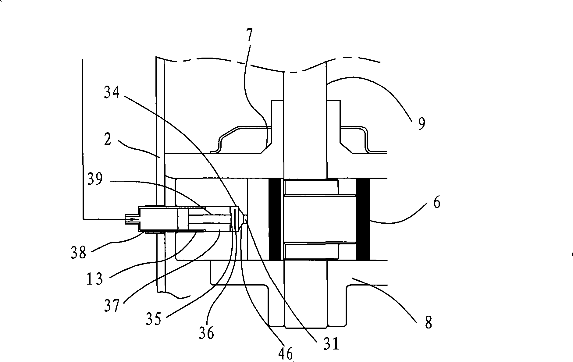
[0044] see Figure 10 , The end of the valve seat body 37 is press-fitted with a valve cover 55 . In addition, the valve cover 55 has the function of the lift stopper 34 . The joint portion between the filling pipe 38 and the valve seat body 37 is joined by welding. This design simplifies the machining of the cylinder cross hole 32, and also has the advantage that the valve stroke s can be adjusted correctly in advance. And it is also possible to more accurately install the refrigerant charging device 13 on the cylinder horizontal hole 32 . Other unmentioned parts are the same as the first embodiment.


PUM


Abstract

The invention discloses a refrigerant charging device of a rotary compressor, which includes a motor arranged in a sealed shell and a compressor pump body connected with the motor, wherein, the compressor pump body includes a cylinder, a main bearing and a supplementary bearing which are respectively arranged at the upper part and the lower part of the cylinder, a crankshaft connected with the motor, a cylinder compression chamber containing a piston which can rotate freely, a slip sheet the front end of which is pressed and connected to the excircle of the piston, and a slip sheet groove for holding the slip sheet; the cylinder, the main bearing or the supplementary bearing of the compressor pump body are provided with the refrigerant charging device, the device is at least provided with a charging hole which is opened on the cylinder compression chamber and a switching valve which responds to the pressure change of the cylinder compression chamber, and the entrance of the refrigerant charging device is connected with the upper space of the shell and/or the exit of an indoor heat exchanger so as to charge gas and/or liquid refrigerant to the cylinder compression chamber. By charging the refrigerant to the cylinder compression chamber, the invention designs the switching valve which automatically controls the charging rate of the refrigerant according to the pressure change of the cylinder compression chamber, with simple and reasonable structure, reliability and cost advantage.

Description

technical field [0001] The invention relates to a rotary compressor, in particular to a refrigerant charging device for a rotary compressor and a control method thereof. Background technique [0002] In order to prevent the rotary compressor mounted on the air conditioner from overheating, and to improve the heating capacity and efficiency, the technology of charging (injecting) refrigerant into the cylinder compression chamber of the compressor is applied. This filling method generally adopts the following method: the refrigerant filling hole arranged on the main bearing or the auxiliary bearing uses the upper or lower moving surface of the piston to achieve the purpose of opening and closing with the rotation of the piston. Therefore, the start and stop of filling depends on the angle of rotation of the piston. In principle, the charging hole cannot communicate with the inner diameter side of the piston during operation, so the diameter of the charging hole is generally l...

Claims


Application Information

Patent Timeline
IPC IPC(8): F04C29/04F04C29/00F04C28/00
Inventor 江波小津政雄杨泾涛
Owner GUANGDONG MEIZHI COMPRESSOR
Why Eureka
Try Eureka