Water-cooled heat exchanger and its manufacturing method

A technology of heat exchanger and manufacturing method, which is applied to evaporator/condenser, refrigerator, refrigeration components, etc., can solve the problems of low outlet water temperature, large volume, and high cost of use, and achieves improved heat exchange effect and heat exchange area. Large, low-cost manufacturing effect

Inactive Publication Date: 2009-01-14
林志辉
View PDF0 Cites 8 Cited by
  • Summary
  • Abstract
  • Description
  • Claims
  • Application Information

AI Technical Summary

Problems solved by technology

The shell-and-tube heat exchanger is composed of a tube bundle and a shell. Water flows in the shell, refrigerant flows in the tubes, and heat exchange is performed in a reverse convection manner. The disadvantage is that the fluid in the shell has a short stroke and the heat exchange efficiency is not high. The outlet water temperature is low, which cannot meet the demand, and the heat exchanger is bulky and expensive
The plate heat exchanger is assembled by pressing corrugated plates with special shapes. Non-metallic gaskets are embedded between the plates. A large number of plates and sealed thermal laminations form many channels between the corrugated plates. Two kinds of media with different temperatures Heat exchange is carried out by flowing in spaced channels. Its disadvantage is that the flow resistance of the fluid is relatively large, and a high-power delivery pump is required to allow the fluid to pass through the heat exchanger, and the cost of use is relatively high. In addition, the manufacture of this heat exchanger The process is complicated and the assembly requirements are high, which leads to the extremely expensive price of the product

Method used


Image

  • Water-cooled heat exchanger and its manufacturing method
  • Water-cooled heat exchanger and its manufacturing method
  • Water-cooled heat exchanger and its manufacturing method

Examples


Embodiment Construction

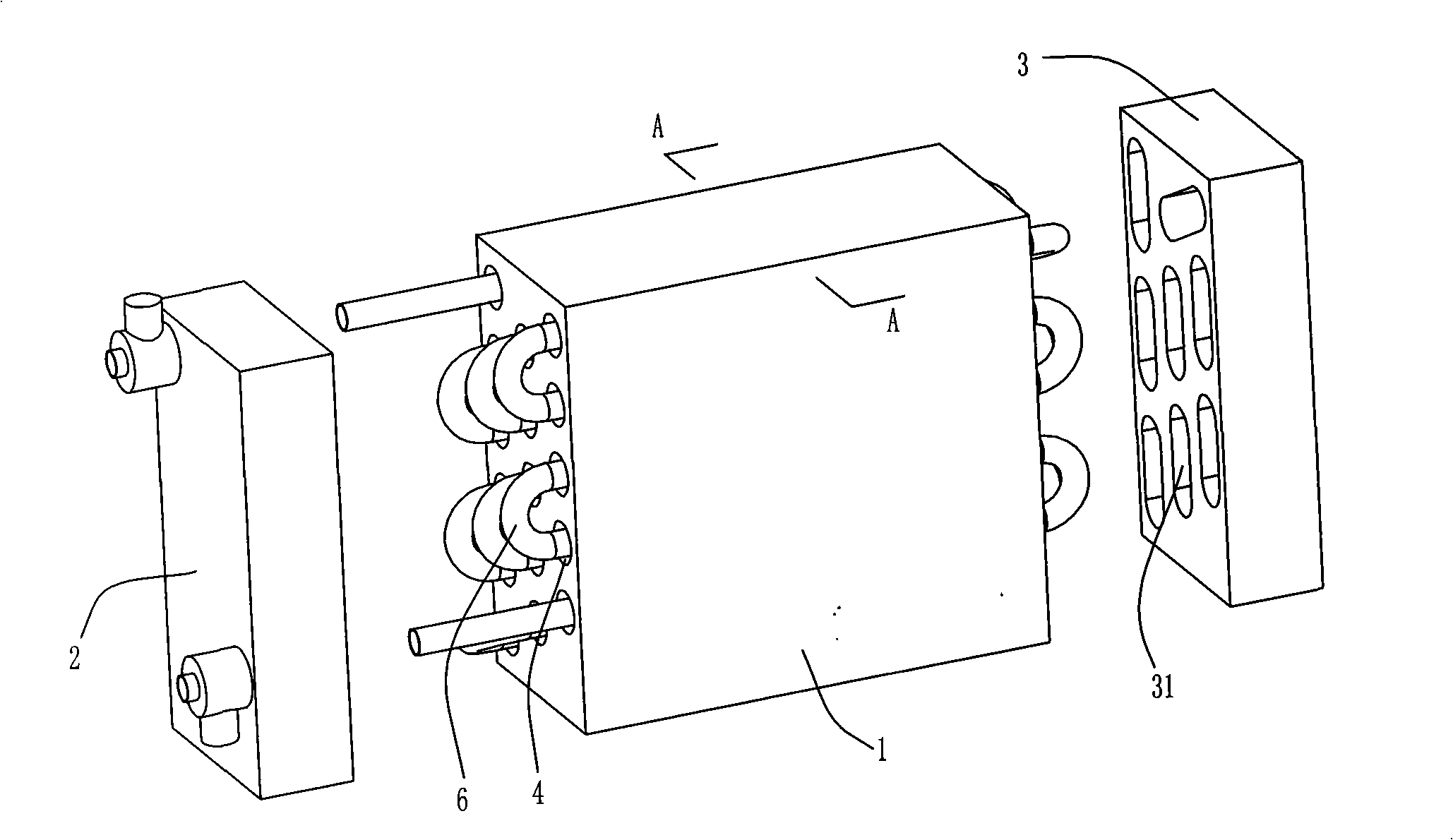
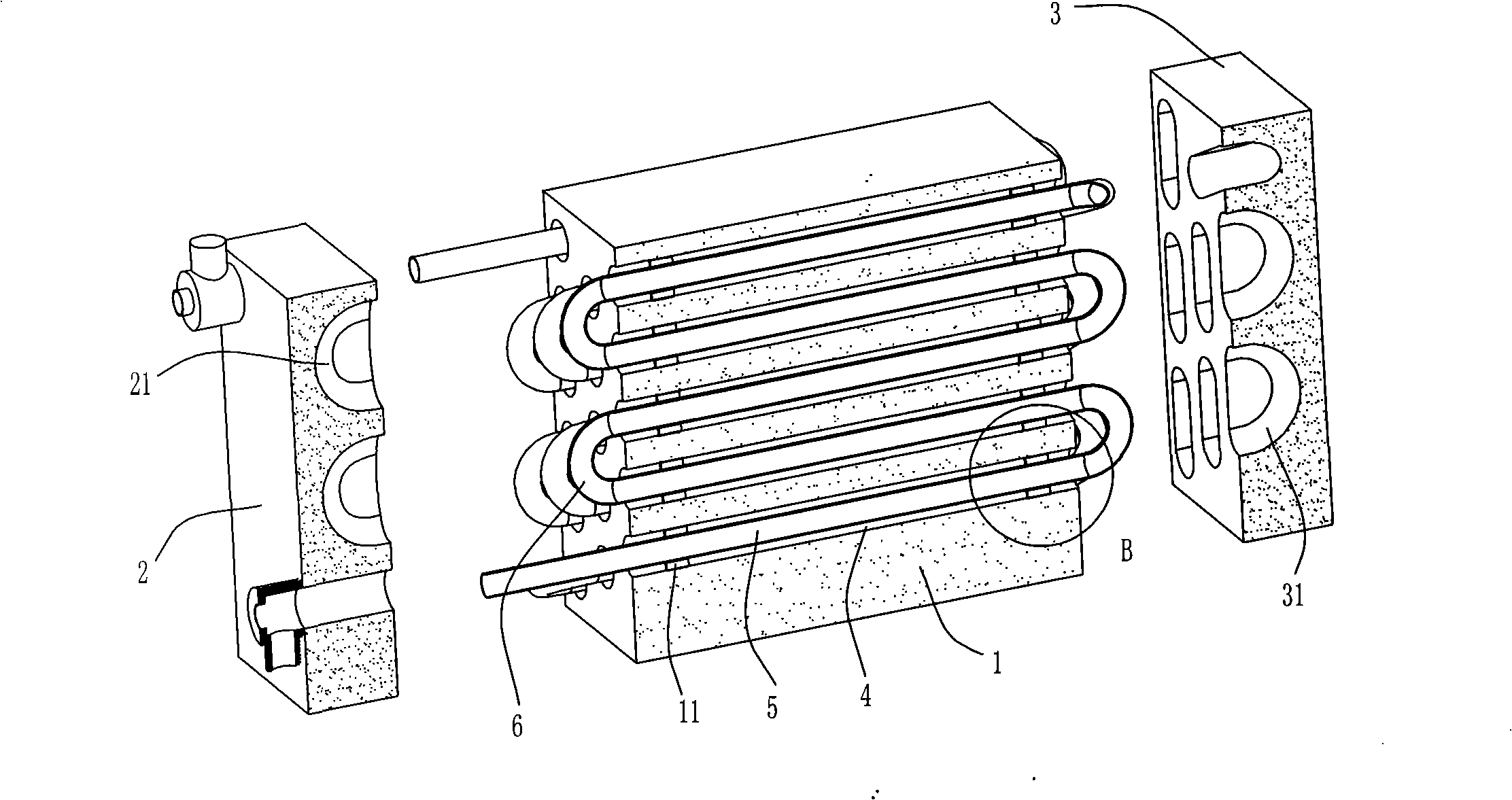
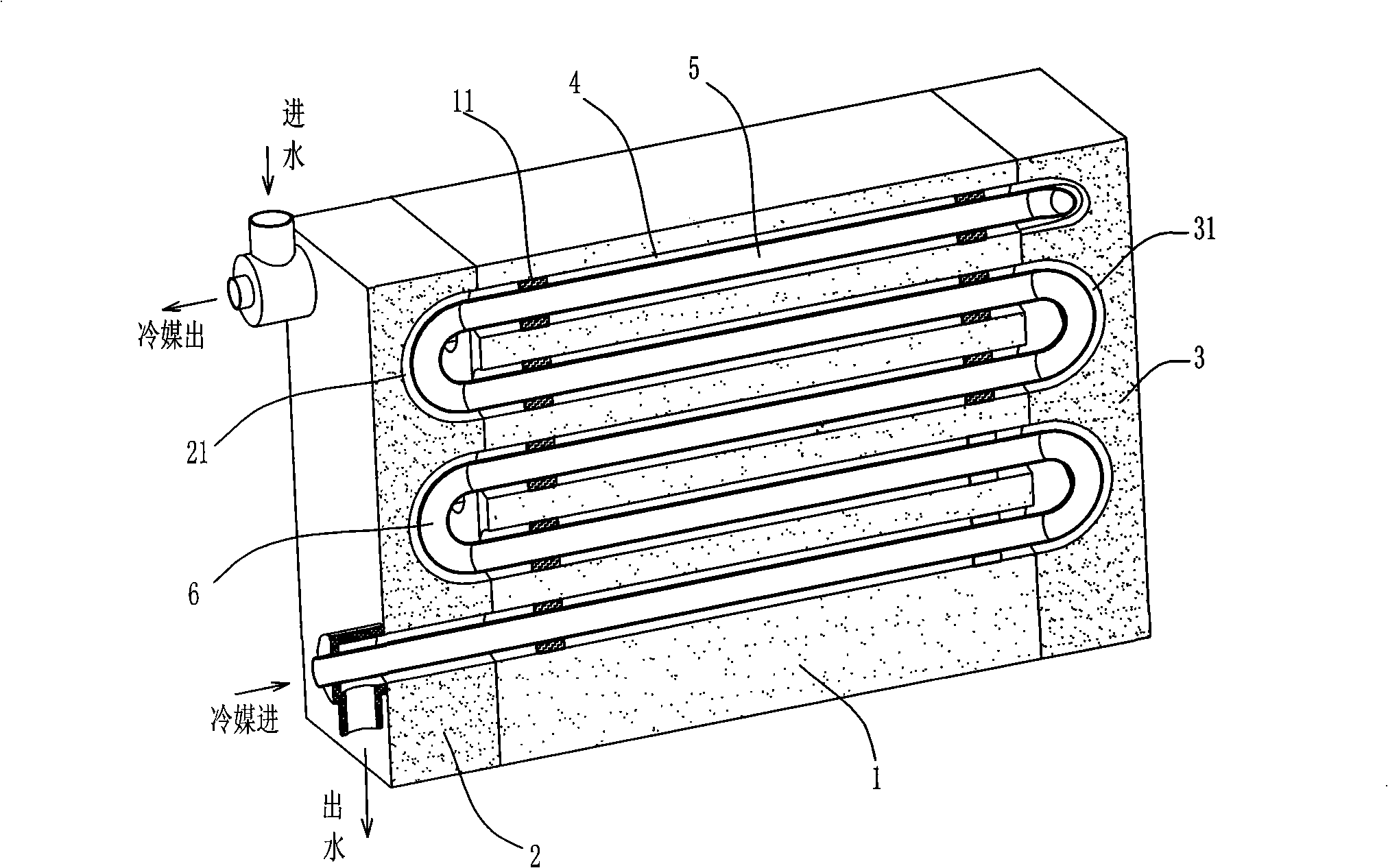
[0020] refer to Figure 1 to Figure 5 , a water-cooled heat exchanger, which includes a main body 1 and front and rear end covers 2, 3, a water flow channel 4 and a refrigerant pipeline 5 are respectively arranged inside the main body 1, and the water flow channel 4 and the refrigerant pipeline 5 inside the main body 1 have respectively Multiple refrigerant pipes are arranged side by side after running through the main body 1. Each refrigerant pipe 5 is placed inside the water flow channel 4. The water flow channels 4 are connected at the front and rear end covers. Each refrigerant pipe 5 is connected at the front and rear ends of the main body 1. The head 6 communicates with at least one other refrigerant pipeline 5 respectively, and each water flow channel 4 communicates with at least one other water flow channel through the water chambers 21 and 31 provided in the front and rear end covers 2 and 3 respectively, and the main body 1 and the front and rear end covers 2 , 3 Sea...


PUM


Abstract

The invention relates to a water-cooled heat exchanger which comprises a main body, a front end cover and a back end cover, wherein, a plurality of water channels and refrigerant pipelines are respectively arranged in the main body and arranged side by side after penetrating the main body, each refrigerant pipeline is arranged in each water channel, the water channels are communicated at the front and the back end covers, each refrigerant pipeline is respectively communicated with at least one another refrigerant pipeline at the front and the back ends of the main body by connectors, each water channel is respectively communicated with at least one another water channel through water cavities which are arranged at the front and the back end covers and in the end covers, the main body is connected with the front and the back end covers in a sealing manner, when in work, the heat exchange is carried out by utilizing the reverse flow of fluid of the inner and the outer layers of the refrigerant pipelines; the designed heat exchanger has simple structure, low manufacturing cost and good heat exchange effect; and the invention further discloses a method for manufacturing the water-cooled heat exchanger.

Description

technical field [0001] The invention relates to a heat exchange device, in particular to a water-cooled heat exchanger and a manufacturing method thereof. Background technique [0002] At present, many heat pump air-conditioning water heaters use water-cooled heat exchangers to prepare hot water, and at the same time replace the function of the condenser to improve work efficiency. The existing water-cooled heat exchangers mainly have two structures: shell-and-tube and plate. . The shell-and-tube heat exchanger is composed of a tube bundle and a shell. Water flows in the shell, refrigerant flows in the tubes, and heat exchange is performed in a reverse convection manner. The disadvantage is that the fluid in the shell has a short stroke and the heat exchange efficiency is not high. The outlet water temperature is low, which cannot meet the demand, and the heat exchanger is bulky and expensive. The plate heat exchanger is assembled by pressing corrugated plates with special...

Claims


Application Information

Patent Timeline
IPC IPC(8): F25B39/00B23P15/26
Inventor 林志辉
Owner 林志辉
Why Eureka
Try Eureka