Track transfer apparatus, track transfer connection device, transfer system and method

A track and transition technology, which is applied in the track system, hoisting device, lifting equipment braking device, etc., can solve the problems of crane instability, walking drive motor easy to burn out, and long time, so as to improve efficiency and simplify transfer. The effect of the course of field operations

Inactive Publication Date: 2009-01-21
SANY MARINE HEAVY IND
View PDF1 Cites 33 Cited by
  • Summary
  • Abstract
  • Description
  • Claims
  • Application Information

AI Technical Summary

Problems solved by technology

[0007] It can be seen from the above description that although the existing technology can realize the overall transition of the RMG, when transitioning, special ground personnel are required to loosen, tighten, and then loosen and retighten the corresponding nuts. For multiple operations, it is necessary to perform multiple manual operations on the corresponding jacking mechanism, that is, the jack, to lift, lower, lift again, and then lower again. It also needs to manually rotate the driving mechanism twice, so the labor intensity of the transition operation Large size, long time, and the coordination and cooperation between the operator in the high-altitude cab and the staff on the ground is required to complete the overall transition of RMG. Therefore, the existing technology cannot meet the requirements of high efficiency and automation of current transportation operations.
[0008] In addition, due to the discontinuity of the track in the track steering gear provided by the prior art, when the crane is traveling, the steel wheels of the traveling mechanism have to pass through two gaps. If the speed is too large, the traveling drive motor will easily burn out; if the speed is too fast, there will be a great impact between the traveling mechanism and the track, which will damage parts such as steel wheels, shafts or bearings, so the discontinuity of the track will easily cause damage to the crane; in addition, The impact during the transition process also makes the crane itself unstable, causing potential safety hazards

Method used


Image

  • Track transfer apparatus, track transfer connection device, transfer system and method
  • Track transfer apparatus, track transfer connection device, transfer system and method
  • Track transfer apparatus, track transfer connection device, transfer system and method

Examples


Embodiment Construction

[0070] The specific implementation of the present invention will be described in detail below in conjunction with the accompanying drawings. The description and description sequence of the specific structure in this part is only a description of specific embodiments, and should not have any limiting effect on the scope of the patent rights of the present invention.

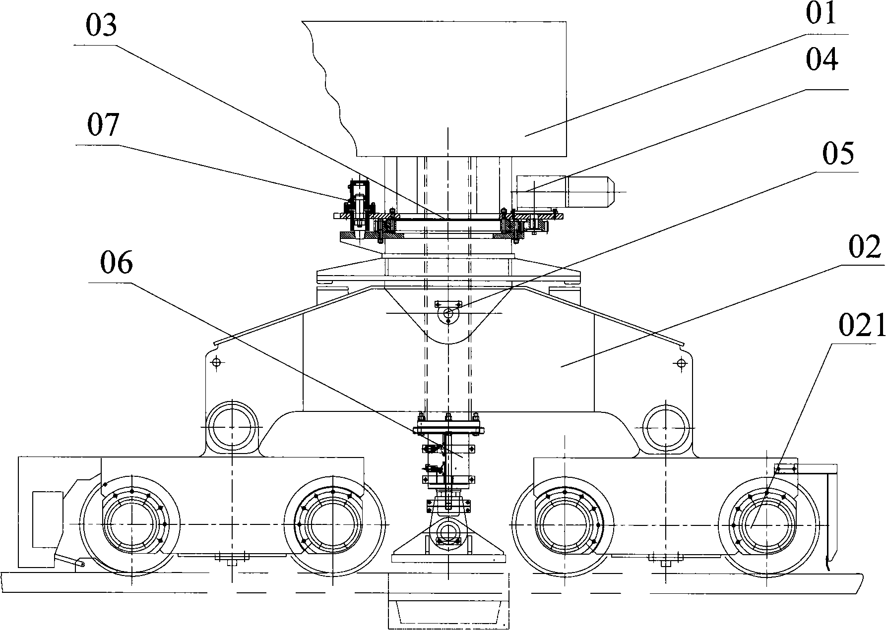
[0071] Such as image 3 As shown, the overall structure schematic diagram of the track transition device provided by Embodiment 1 of the present invention, the device includes: the driving mechanism 02 including the steel wheel 021, the first slewing bearing 03 connecting the saddle beam 01 and the driving mechanism 01, the first slewing The driving mechanism 04, the connecting hinge shaft 05 that articulates the driving mechanism 02 and the outer ring of the first slewing bearing 03, the locking mechanism 07 and the jacking mechanism 06, for the convenience of description, the saddle beam 01 is also shown in the fig...


PUM


Abstract

The invention discloses a rail transfer device. The device comprises a traveling mechanism comprising steel wheels, a first gyration mechanism connecting a saddle beam and the driving mechanism, a first gyration driving mechanism and a jacking-up mechanism, wherein the first gyration mechanism can rotatablely connect the traveling mechanism and the saddle beam; the first gyration driving mechanism can drive the driving mechanism to rotate relative to the saddle beam; the jacking-up mechanism is a jacking-up hydraulic cylinder comprising a cylinder body and a piston; the cylinder body and the saddle beam are relatively fixed; the outer end of the piston is provided with support legs; when the piston of the jacking-up hydraulic cylinder extends out, the support legs can jack the saddle beam up; and the device also comprises a grasping mechanism capable of grasping movable rails. In addition, the invention also discloses a rail transfer connecting device, a rail-type gantry crane transfer system and a transfer method thereof. The rail transfer device provided by the invention can realize the automation of transfer operation and improve the working efficiency of the transfer operation.

Description

technical field [0001] The present invention relates to an overall transition technology for a large crane, in particular to a track transition device and a track-type gantry crane, and also relates to a track transition connection device, a track-type gantry crane transition system and its transition field method. Background technique [0002] At present, the rail-mounted gantry crane (RMG) is being more and more widely used due to its high site utilization rate, high positioning ability, easy automation, no exhaust noise pollution by electric power, and simple operation and maintenance. Among them, the wharf Yard operation is the most common working scene where RMG is applied. Generally speaking, there will be several working sites in the dockyard, and each working site is laid with tracks, and RMGs are set on the tracks. Sometimes, multiple RMGs are installed on the same working site track in order to improve the working efficiency. However, when a storage yard is full,...

Claims


Application Information

Patent Timeline
Patent Type & Authority Applications(China)
IPC IPC(8): B66C5/02B66C7/12B66C7/00B66C9/14B66C17/00
Inventor 彭国成李翠英张志国吴乐尧王力文潘国智钟礼平
Owner SANY MARINE HEAVY IND
Why Eureka
Try Eureka