Permanent magnet type vacuum circuit-breaker

A vacuum circuit breaker, permanent magnet technology, applied in the direction of high-voltage air circuit breakers, circuits, electrical components, etc., can solve the problem of short force arm, etc., achieve simple and easy operation, ensure stability and reliability, and reduce costs Effect

Inactive Publication Date: 2014-04-23
华精科技股份有限公司
View PDF6 Cites 0 Cited by
  • Summary
  • Abstract
  • Description
  • Claims
  • Application Information

AI Technical Summary

Problems solved by technology

[0002] Chinese patent 200620004381.1 discloses a permanent magnet indoor high-voltage vacuum circuit breaker. It can be seen from the accompanying drawings that it includes three vacuum circuit breaker bodies and a permanent magnet operating mechanism; each of the vacuum circuit breaker bodies includes vacuum arc extinguishing room, moving contact, static hoe, insulating pull rod connected with the moving contact; the permanent magnet operating mechanism includes three transmission components, a main shaft for driving the corresponding insulating pull rod to move up and down through the rotating component, and a A permanent magnet driving mechanism for driving the main shaft to rotate, and two breaking spring assemblies; the permanent magnetic driving mechanism includes a driving rod, and the lower end of the driving rod drives the main shaft to rotate through a driving crank arm; the transmission assembly It includes a transmission crank arm, a crank arm connecting plate, a transmission arm, and a positioning pin; the transmission crank arm is fixed on the main shaft; one end of the crank arm connecting plate is rotatably connected with the transmission crank arm, and the other end is rotated with one end of the transmission arm connected, the other end of the transmission arm is rotationally connected with a corresponding insulating pull rod, the middle part of the transmission arm is provided with a shaft hole, and there is also a A hook hole; the positioning pin shaft is statically arranged relative to the circuit breaker housing and passes through the shaft holes of each transmission arm; each breaking spring assembly includes a breaking spring support plate fixed on the circuit breaker housing, Break spring; the upper end of the break spring is hooked on the break spring support plate, and the lower end of the break spring is hooked in the hook hole on the transmission arm; the disadvantage of this structure is that the lower end of the break spring is directly hooked Hanging on the transmission arm, its moment arm is relatively short, so it is necessary to use a breaking spring that can provide a large elastic force, which increases the cost to a certain extent; in addition, because the breaking spring is directly hooked on the driving arm, the breaking spring is applied to the The elastic force on the arm has a direct impact on the opening and closing technical effect of the dynamic and static contacts in the vacuum circuit breaker body, while in the same permanent magnet vacuum circuit breaker, each breaking spring is easily affected by the installation positioning, and will There is a large difference in the elastic parameters provided, and long-term use will easily affect the stability and reliability of the entire permanent magnet operating mechanism

Method used


Image

  • Permanent magnet type vacuum circuit-breaker
  • Permanent magnet type vacuum circuit-breaker

Examples


Embodiment 1

[0024] (Example 1, permanent magnet vacuum circuit breaker)

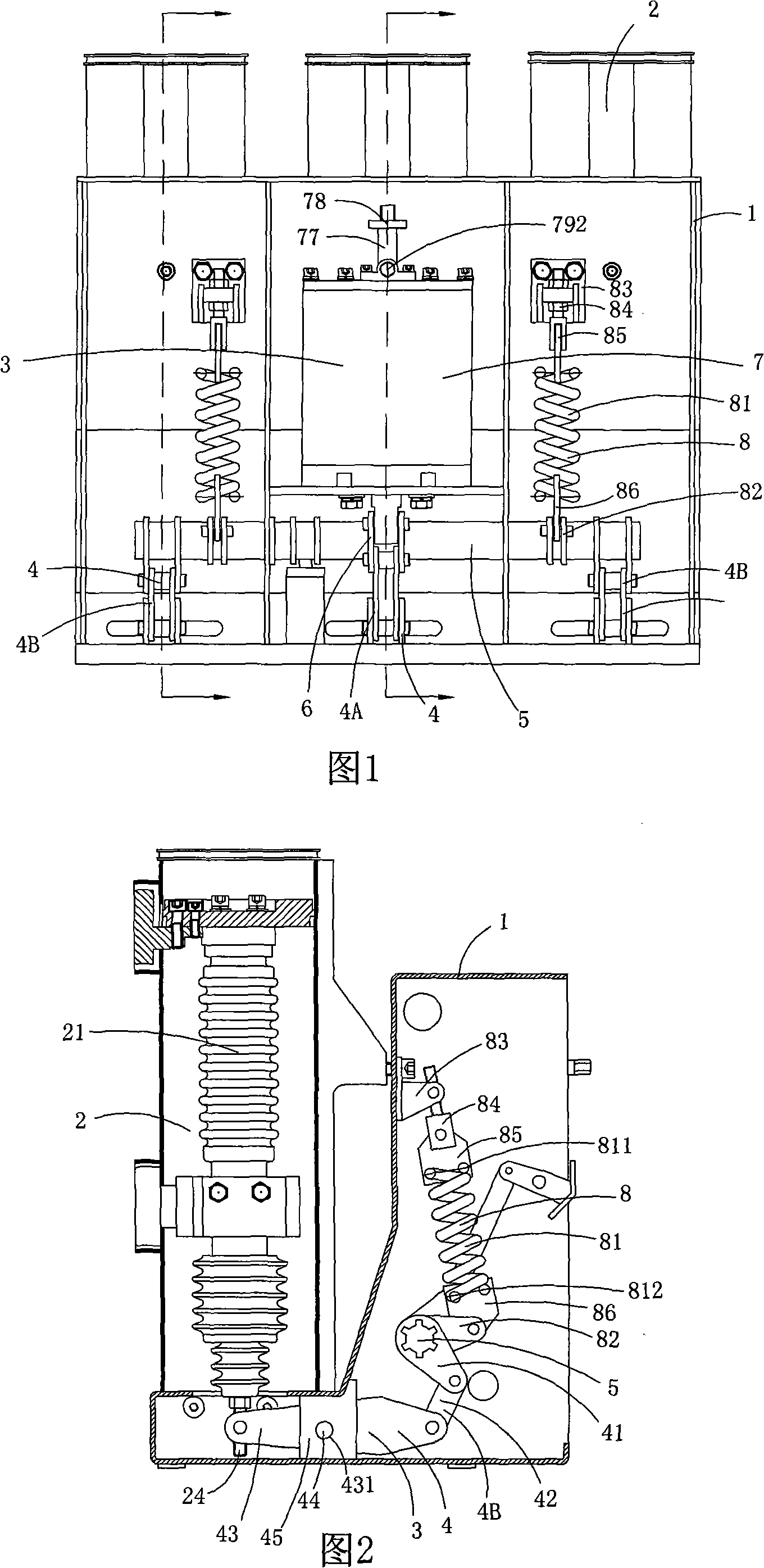
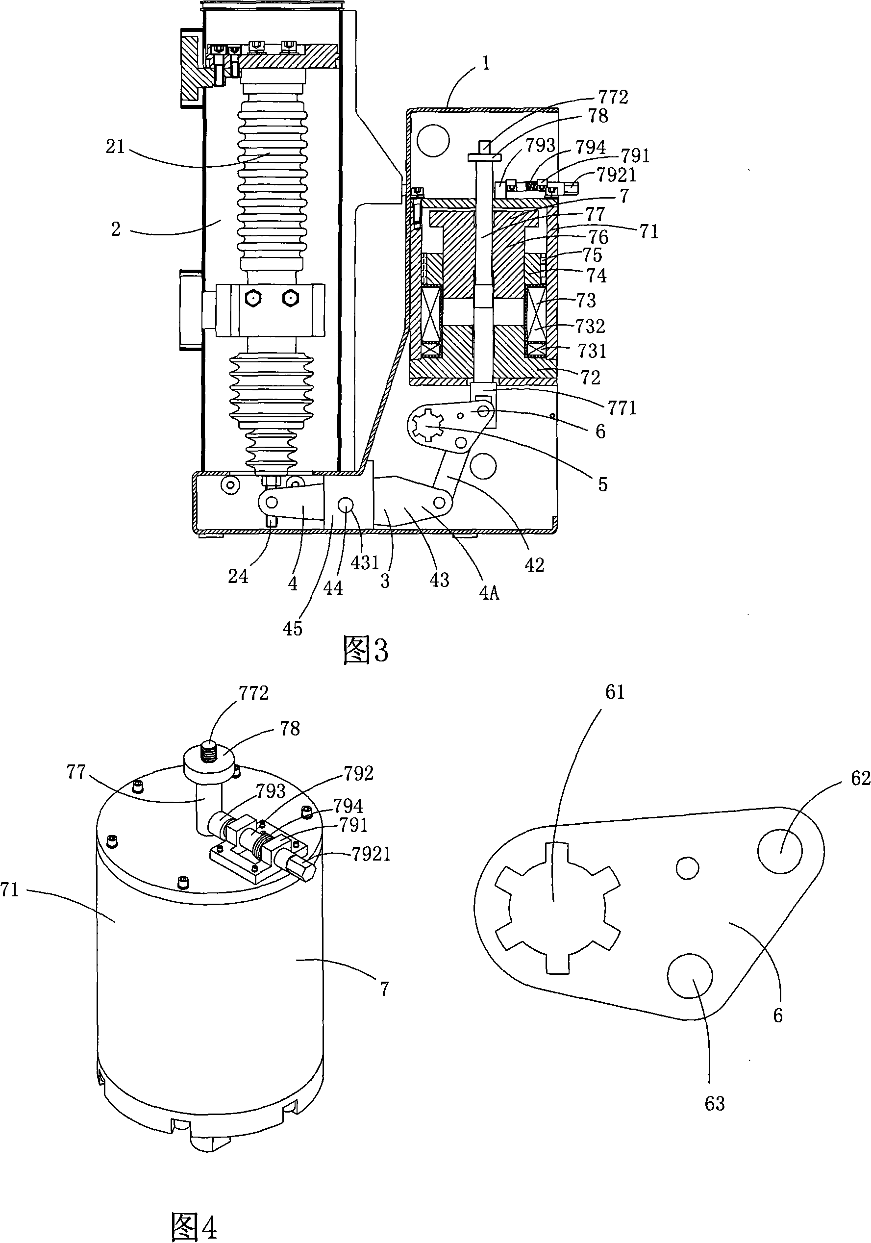
[0025] Figure 1 to Figure 4 A specific embodiment of the invention is shown; wherein, figure 1 It is a structural schematic diagram of the present invention, figure 2 yes figure 1 The schematic diagram of the cross-sectional structure of the permanent magnet vacuum circuit breaker along the line A-A; image 3 yes figure 1The schematic diagram of the cross-sectional structure of the permanent magnet vacuum circuit breaker along the line B-B; Figure 4 yes figure 1 A schematic diagram of a three-dimensional structure of the permanent magnet drive mechanism in the permanent magnet vacuum circuit breaker shown; Figure 5 yes image 3 A structural schematic diagram of the driving crank arm in the permanent magnet vacuum circuit breaker shown.

[0026] See Figure 1 to Figure 5 , this embodiment is a permanent magnet high voltage vacuum circuit breaker, including a circuit breaker housing 1, three vacuum circui...


PUM


Abstract

The invention discloses a permanent-magnet vacuum circuit breaker, which comprises a circuit breaker shell body, three vacuum circuit breaker bodies and a permanent-magnet actuating mechanism, wherein each vacuum circuit breaker comprises a vacuum arc-extinguishing chamber, a movable contact, a fixed contact and an insulation draw rod which is connected with the movable contact, the permanent-magnet actuating mechanism comprises three driving components, a main shaft, a driving turn arm which is arranged on the middle portion of the main shaft, a permanent-magnet driving mechanism which is used for driving the main shaft to rotate, and two breaking spring assemblies, wherein the two breaking spring assemblies are symmetrically arranged on both sides of the driving turn arm, each breaking spring assembly comprises a breaking spring and a breaking spring driving turn arm, wherein the breaking spring driving turn arm is fixed on the main shaft, the upper end of the breaking spring is correspondingly fixed with the shell body of the circuit breaker, and the lower end thereof is connected with the breaking spring driving turn arm. The invention has the advantages that the stability and the reliability are effectively guaranteed during the long-term use, simultaneously, the cost is reduced as much as possible, and the service life of the whole machine is prolonged.

Description

technical field [0001] The invention belongs to the technical field of circuit breakers, and in particular relates to a permanent magnet vacuum circuit breaker. Background technique [0002] Chinese patent 200620004381.1 discloses a permanent magnet indoor high-voltage vacuum circuit breaker. It can be seen from the accompanying drawings that it includes three vacuum circuit breaker bodies and a permanent magnet operating mechanism; each of the vacuum circuit breaker bodies includes vacuum arc extinguishing room, moving contact, static hoe, insulating pull rod connected with the moving contact; the permanent magnet operating mechanism includes three transmission components, a main shaft for driving the corresponding insulating pull rod to move up and down through the rotating component, and a A permanent magnet driving mechanism for driving the main shaft to rotate, and two breaking spring assemblies; the permanent magnetic driving mechanism includes a driving rod, and the l...

Claims


Application Information

Patent Timeline
Patent Type & Authority Patents(China)
IPC IPC(8): H01H33/66H01H33/666H01H33/664H01H33/38
Inventor 童建朋童瑶阳童余阳童微微童杨扬
Owner 华精科技股份有限公司
Why Eureka
Try Eureka