
DC great current deicing apparatus with static state reactive compensation function

A static reactive power compensation, high current technology, applied in reactive power compensation, output power conversion devices, AC power input conversion to DC power output, etc., can solve problems such as difficult conversion control, reduce supporting costs, and achieve reasonable structure. , switch the effect of simple operation

Active Publication Date: 2009-01-21
ZHEJIANG GUIRONG XIEPING TECH
View PDF0 Cites 27 Cited by
  • Summary
  • Abstract
  • Description
  • Claims
  • Application Information

AI Technical Summary

Problems solved by technology

If the DC high-current ice-melting technology can be combined with the static reactive power compensation device, it will effectively improve the utilization rate of the equipment, and it can also solve the problem of needing additional rectification and filtering devices in the existing DC high-current ice-melting technology. However, there is no corresponding device development and application at present, and the traditional static var compensation device uses a thyristor controlled reactor and a fixed-input passive filter structure, and it is difficult to achieve conversion control

Method used


Image

  • DC great current deicing apparatus with static state reactive compensation function
  • DC great current deicing apparatus with static state reactive compensation function
  • DC great current deicing apparatus with static state reactive compensation function

Examples


Embodiment Construction

[0020] The present invention will be further described below in conjunction with the accompanying drawings:

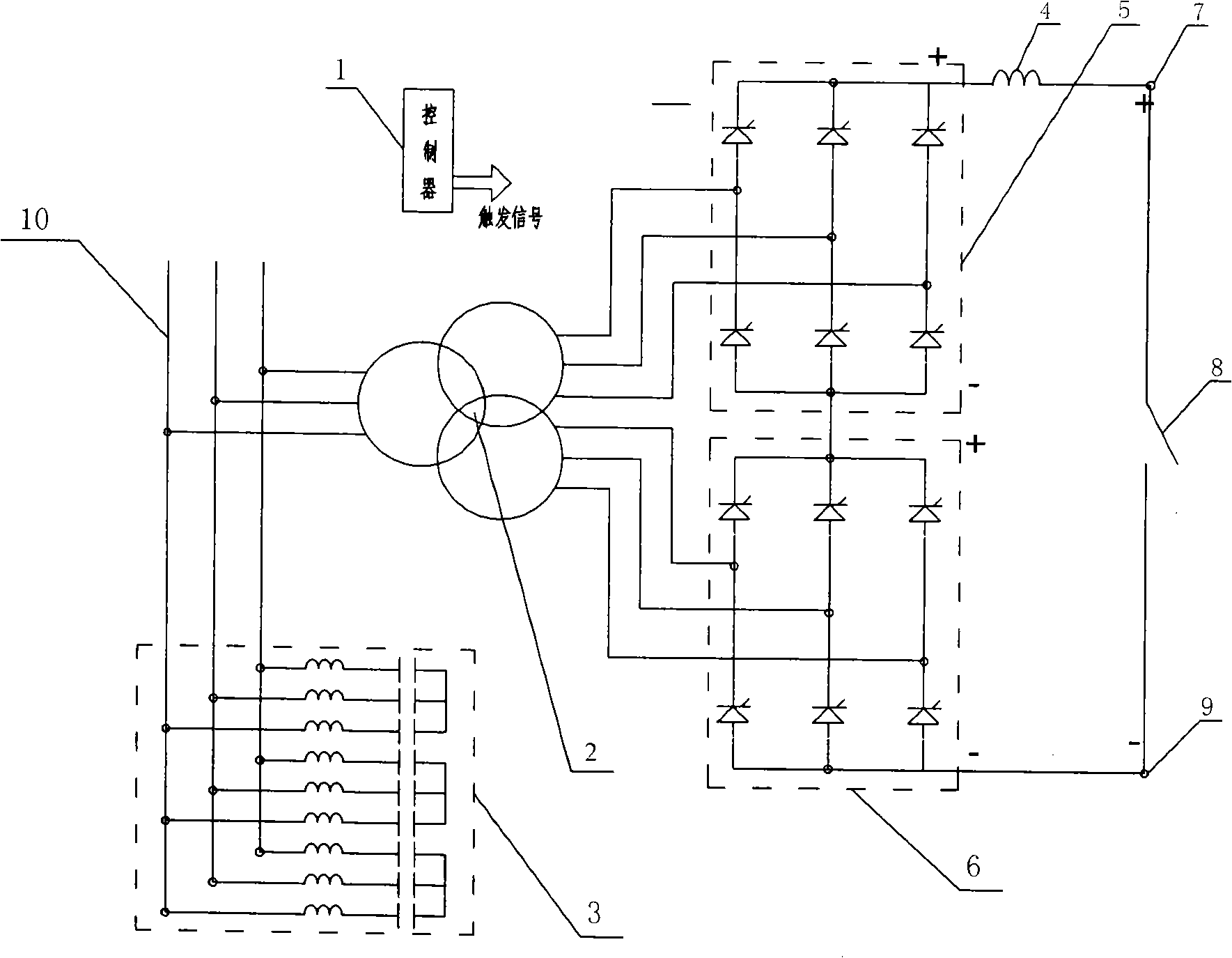
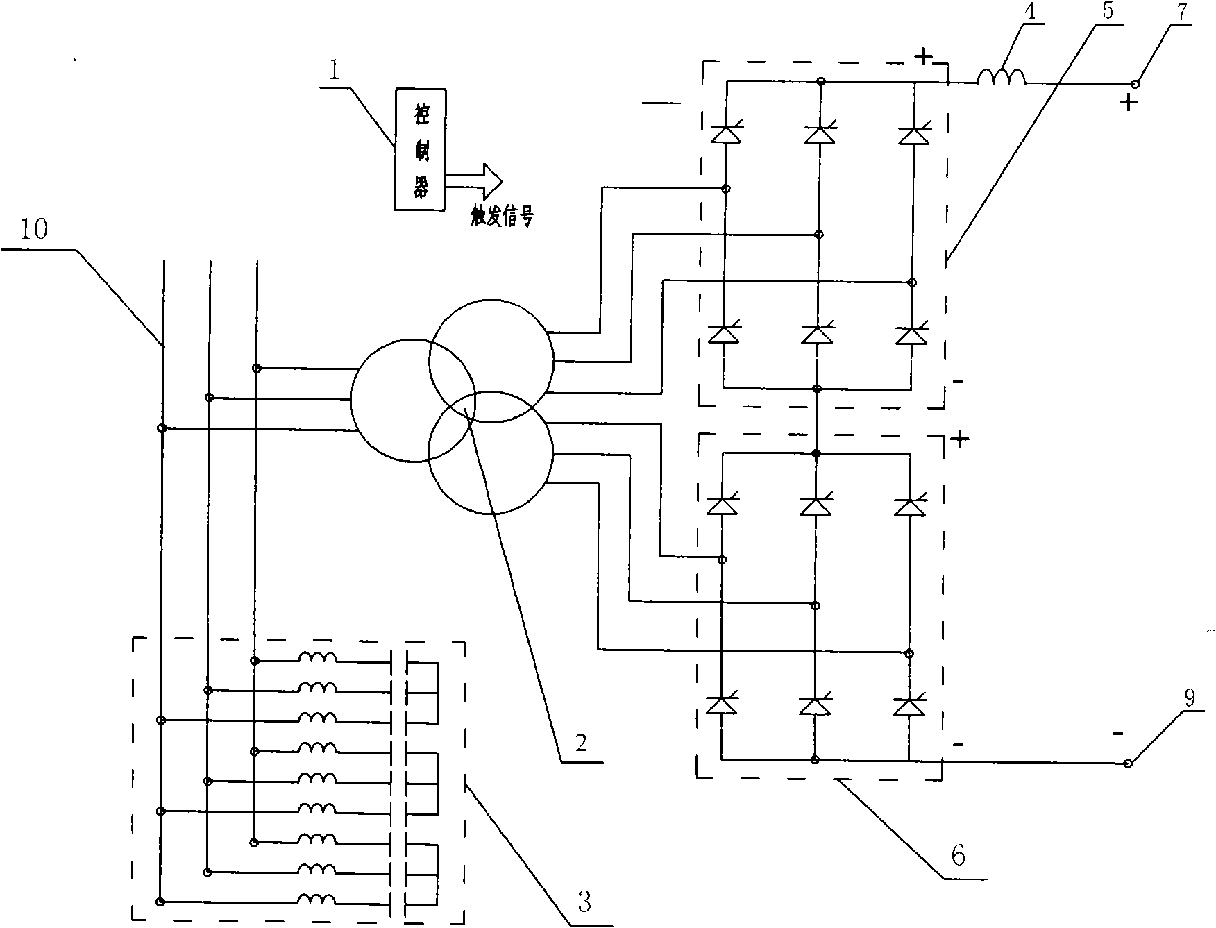
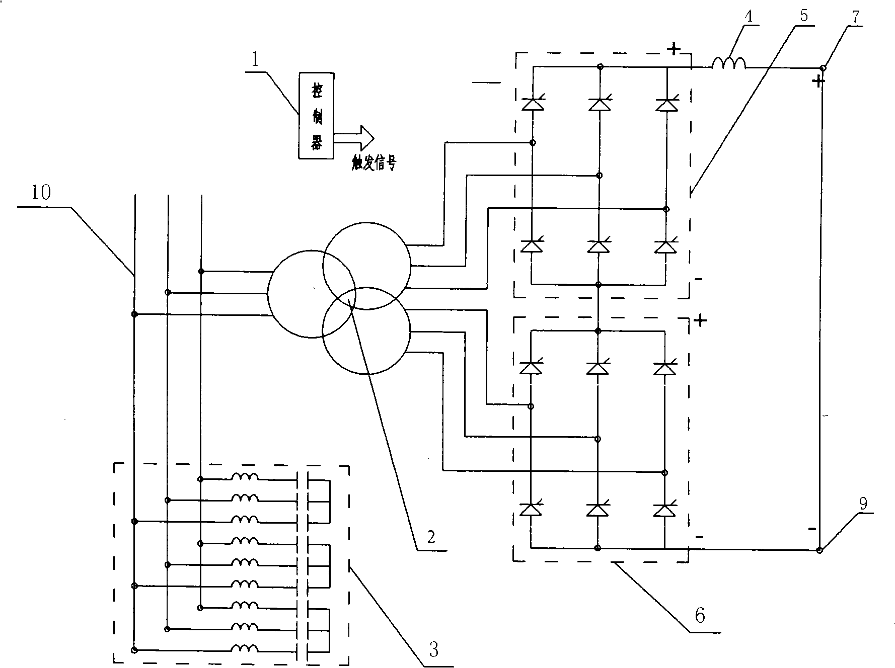
[0021] like figure 1 Shown is a DC high-current ice melting device with static reactive power compensation function. The primary side of the three-winding rectifier transformer 2 is connected to the three-phase bus in parallel, and the two secondary sides are connected in star and delta respectively. 30° and the same amplitude, and the two secondary sides are respectively connected to the middle point of the positive-end three-phase high-voltage high-current thyristor valve 5 and the negative-end three-phase high-voltage high-current thyristor valve 6 . The main body of each phase is a series of thyristor valves, and each phase of the thyristor valve has three external electrical connection terminals. , respectively positive, negative and middle points, the middle point is the AC side, the middle point and the positive and negative thyristors connected in series are t...


PUM


Abstract

The invention provides a DC high-current ice-melting device with static reactive-load compensation function, pertaining to the technical field of supporting equipments of high / low voltage power supply / distribution systems. The primary side of a three-winding rectification transformer is merged on a three-phase bus, two secondary sides are respectively connected with the intermediate points of a positive-end three-phase high-voltage high-current controllable silicon valve and a negative-end high-voltage high-current controllable silicon valve; the anodes and cathodes of the two three-phase high-voltage and high-current controllable silicon valves form a 12-pulse rectifier; the anode of the positive-end three-phase high-voltage high-current controllable silicon valve is connected to a DC reactor in series to achieve a positive terminal, and the cathode of the negative-end high-voltage high-current controllable silicon valve forms a negative terminal, a shorting stub is arranged between the positive terminal and the negative terminal. The invention integrates DC high-current ice-melting technology and static reactive-load compensation function, thereby, the device can not only be used as a static reactive-load compensation device, but also be used as a current-controllable DC high-current ice-melting device; as a result, the cost of supporting equipment for low / high voltage supply / distribution system is reduced remarkably, and the utilization ratio of the equipment is largely improved.

Description

technical field [0001] The invention belongs to the technical field of supporting equipment for high and low voltage power supply and distribution systems, and in particular relates to a DC high current ice melting device with a static reactive power compensation function. Background technique [0002] Accidents such as disconnection of high-voltage transmission lines, tower collapse, and pole collapse occur frequently due to icing and snow accumulation on transmission lines. The disconnection and tower collapse of high-voltage transmission lines seriously affect the safe operation of the power grid, resulting in large-scale power outages. In order to prevent the occurrence of such accidents, it is necessary to melt the ice and snow on the wires in time. At present, there are two main types of ice melting methods: mechanical (vibration) and electric heating. Mechanical (vibration) ice melting, that is, using vibrating wires to make ice and snow fall off, is characterized by ...

Claims


Application Information

Patent Timeline
IPC IPC(8): H02G7/16H02M1/42H02M1/12H02M7/155
CPCY02B70/126Y02B70/10Y02E40/30
Inventor 梁一桥
Owner ZHEJIANG GUIRONG XIEPING TECH
Learn More