Water cooling electric machine for vehicle

A water cooling and vehicle technology, applied in cooling/ventilation devices, electromechanical devices, electrical components, etc., can solve the problems of large volume and poor heat dissipation effect, and achieve the effect of strengthening cooling effect, small thermal resistance and high safety.

Inactive Publication Date: 2009-01-21
WUXI KIPOR POWER CO LTD
View PDF0 Cites 14 Cited by
  • Summary
  • Abstract
  • Description
  • Claims
  • Application Information

AI Technical Summary

Problems solved by technology

However, due to the large size and poor heat dissipation effect of the conventional air-cooled motor, it is difficult to meet the needs of such occasions.

Method used


Image

  • Water cooling electric machine for vehicle
  • Water cooling electric machine for vehicle
  • Water cooling electric machine for vehicle

Examples


Embodiment Construction

[0022] Below the present invention will be further described in conjunction with the embodiment in the accompanying drawing:

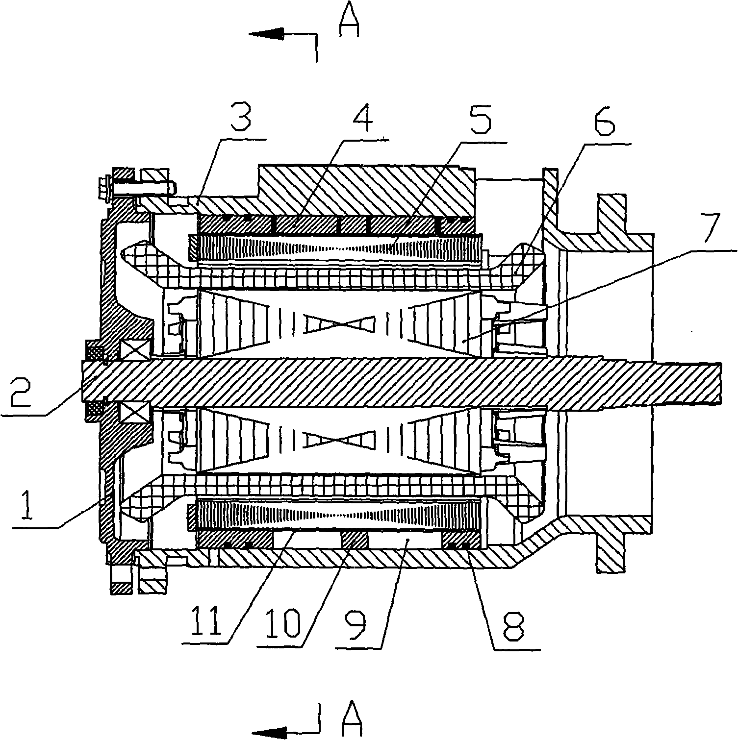
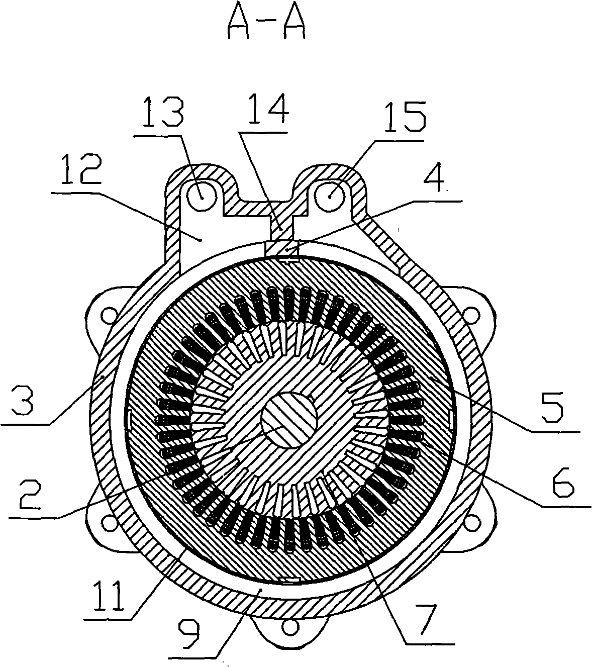
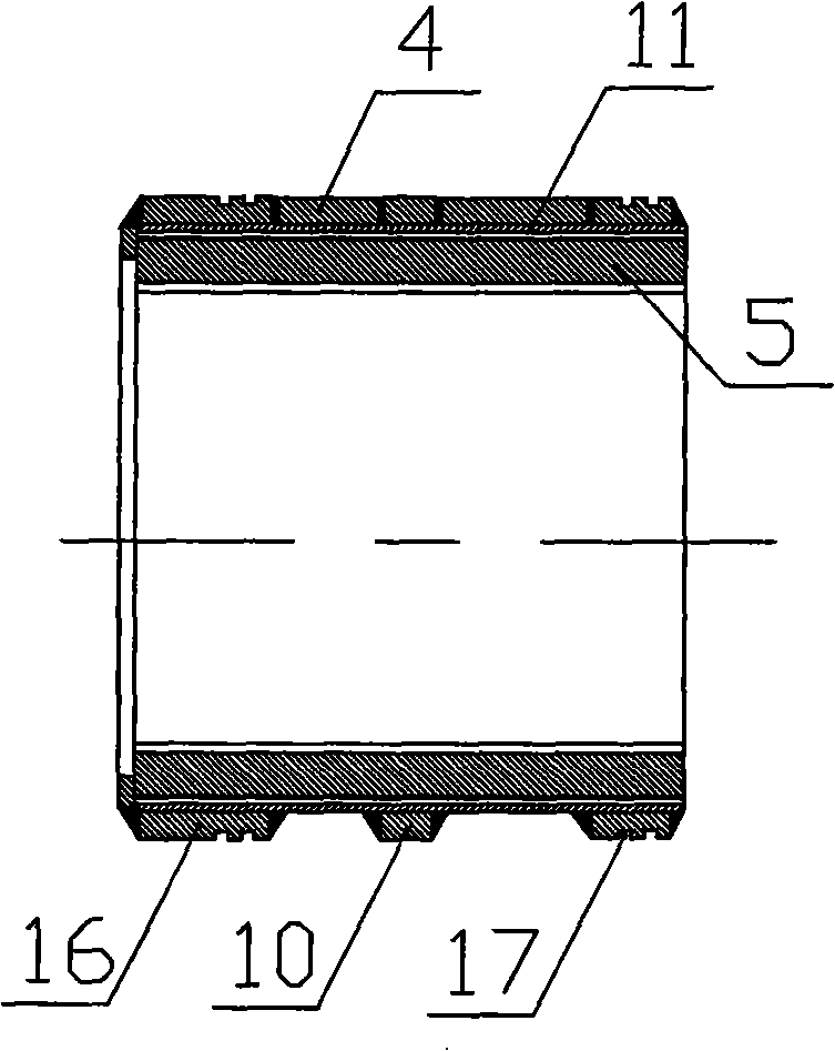
[0023] Such as Figure 1 to Figure 4 Shown is the first embodiment of the present invention. It mainly includes end cover 1, motor shaft 2, motor casing 3, axial partition 4, stator core 5, stator winding 6, rotor 7, sealing ring 8, cooling water cavity 9, circumferential hoop 10, circumferential water tank 11. Water collection cavity 12, water inlet 13, longitudinal rib 14, water outlet 15, side plate 16 and sealing groove 17, etc.

[0024] In the present invention, the motor shaft 2 is arranged in the motor casing 3, and the rotor 7 is installed on the motor shaft 2, and the rotor 7 is composed of a rotor iron core and a rotor winding. The stator composed of stator winding 6 and stator core 5 is installed outside the rotor 7, and the end cover 1 is installed at the end of the motor casing 3, and a cooling water cavity 9 is arranged between the moto...


PUM


Abstract

The present invention relates to a water cooling motor of engineering vehicle. In the technical proposal, a motor shaft is arranged in a motor shell, and is provided with a rotor; the outside of the rotor is provided with a stator which consists of a stator winding and a stator core; and an end cover is arranged at the end of the motor shell. The water cooling motor is characterized in that a cooling water cavity is arranged between the motor shell and the stator core and; the cooling water cavity is connected with a water inlet and a water outlet, which are arranged on the motor shell. The stator core is connected with a peripheral sink; two ends of the peripheral sink are connected with a side plate; and the external surface of the side plate is provided with a sealing groove. The water cooling motor has the advantages of small size, excellent performance of heat dissipation, high cooling speed, low temperature rise, and high security. Moreover, the water cooling motor can effectively prevent the leakage of cooling water, temporarily store the cold water flowing inwards and the hot water flowing outwards, guarantee the circulating use of the cooling water, and satisfy the requirements of electrically driven engineering vehicles.

Description

technical field [0001] The invention relates to a water-cooled motor for engineering vehicles, in particular, it can be widely used in water-cooled motors used on engineering vehicles such as electric drive loaders, excavators, and forklifts. Background technique [0002] The electric transmission of engineering vehicles refers to the transmission system in which the electric motor is driven by electric energy, and the driving wheel is driven by the electric motor. The electric energy can be the electric energy generated by the generator driven by the engine, or the electric energy from the storage battery. For engineering vehicles using electric transmission, due to the limited chassis space, it is generally required to use a motor with a small volume and good heat dissipation performance in order to arrange the drive train reasonably and effectively. However, the conventional air-cooled motor is difficult to be used in such occasions due to its large volume and poor heat ...

Claims


Application Information

Patent Timeline
Patent Type & Authority Applications(China)
IPC IPC(8): H02K9/19H02K5/20
CPCH02K5/20H02K5/203
Inventor 肖亨琳
Owner WUXI KIPOR POWER CO LTD
Why Eureka
Try Eureka