Method for polishing inner concave surface of optical elements as well as device

A technology for optical components and polishing devices, which is applied to optical surface grinders, grinding/polishing equipment, and polishing compositions containing abrasives, etc., which can solve the problem that the workpiece has a limited swing range, the polishing wheel cannot be inserted into the cavity, and cannot adapt to processing and other issues to achieve the effect of high practical value

Inactive Publication Date: 2009-01-28
TSINGHUA UNIV
View PDF0 Cites 42 Cited by
  • Summary
  • Abstract
  • Description
  • Claims
  • Application Information

AI Technical Summary

Problems solved by technology

[0004] However, this commercial magnetorheological polishing method has certain limitations in polishing the inner concave surface. It uses a fixed polishing wheel, and the workpiece rotates and swings for processing. It is suitable for processing the convex surface of axisymmetric optical elements, but it cannot adapt to the deep surface with a small radius of curvature. For the processing of concave surfaces, especially the concave surface of the conformal optical dome, the polishing wheel cannot extend into the cavity, or the swing range of the workpiece is limited, which cannot meet the processing of the entire concave surface

Method used


Image

  • Method for polishing inner concave surface of optical elements as well as device
  • Method for polishing inner concave surface of optical elements as well as device
  • Method for polishing inner concave surface of optical elements as well as device

Examples


Embodiment 1

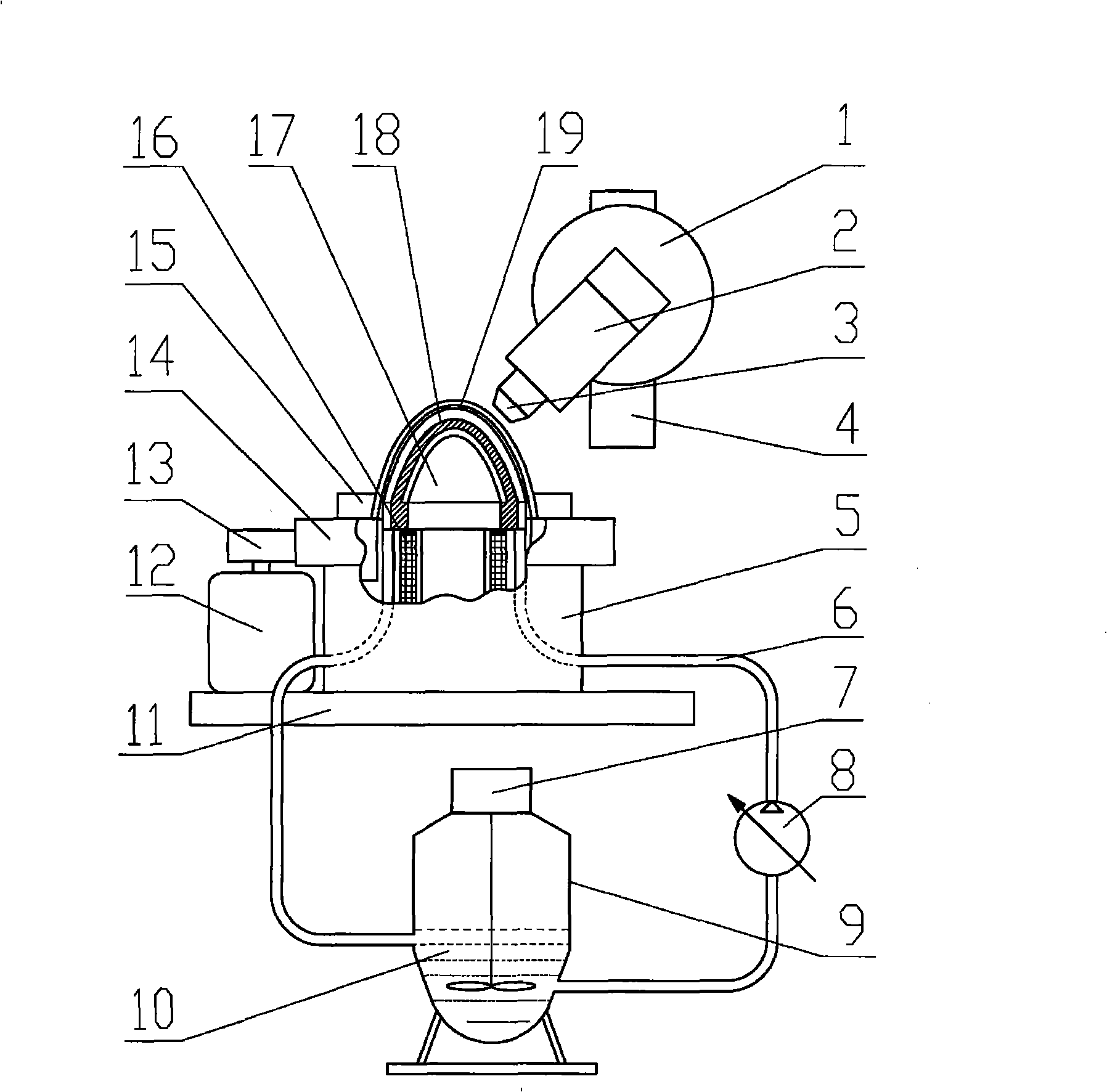
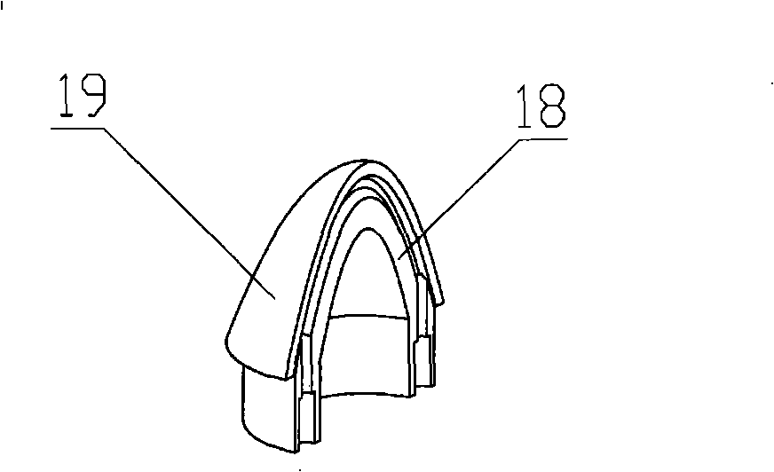
[0028] figure 1 It is a structural schematic diagram of the device of the present invention, figure 2It is a schematic diagram of the positional relationship between the slotted mandrel and the workpiece to be processed. The polishing turntable base 5 is fixedly connected with the CNC XY workbench 11, and the inner magnetic pole excitation coil 16, the inner magnetic pole core 17 and the mandrel 18 are integrally fixed on the numerical control XY workbench 11 and kept concentric with the polishing turntable base 5; 15 Fix the workpiece 19 on the polishing turntable 14, the polishing turntable 14 and the polishing turntable base 5 are connected by bearings, so that together with the workpiece 19, they rotate under the action of the turntable drive motor 12 and the transmission wheel 13, and the rotating central axis and the mandrel The axes of 18 are coincident, and keep a small gap between the inner concave surface of the workpiece 19 and the mandrel 18, and the two surfaces...

Embodiment 2

[0035] In this embodiment, the inner magnetic pole iron core 17 of the inner concave surface polishing device for optical elements adopts the form of permanent magnet instead of the inner magnetic pole excitation coil 16, and the outer magnetic pole tool head 3 also adopts the form of permanent magnet, which is changed by adjusting the distance from the magnetic pole to the processing area. magnetic field strength. The device structure and processing method of other parts are the same as those in Example 1.

Embodiment 3

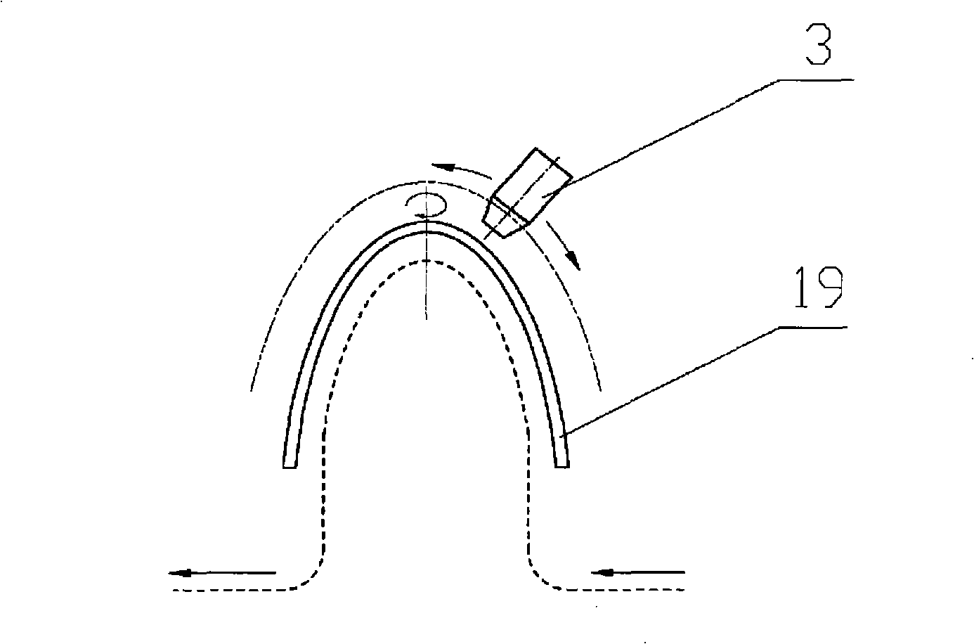
[0037] In this embodiment, the outer magnetic pole tool head 3 of the optical element inner concave surface polishing device adopts a multi-pole composite magnetic pole head, and can rotate around its own central axis to form a rotating external strengthening magnetic field. The device structure and processing method of other parts are the same as those in Example 1.


PUM


Abstract

The invention belongs to the technical field of precision optical polish finish, in particular to a polishing method of the inner concave surface of optical elements and a polishing device. A core mould with a tank circuit and inosculating with the shape of the inner concave surface to be processed is fixed below the inner concave surface of a work piece to be processed, and the work piece rotates around the own rotary shaft, keeps a micro clearance from the core mould and applies magnetic fields to processing regions by an external magnetic pole tool head and an internal magnetic pole exciting coil. When magneto-rheological fluids with polishing abrasives flow through the processing region along the tank circuit, a flexible polishing head is formed under the action of magnetic field and absorbed on the inner concave surface and polishing effects are generated. The polishing method and the device can realize the inner concave surface polishing of conformal optical elements with small curvature radiuses or deep cavity structure and other cyclically symmetric high gradient aspheric surfaces, and can remove distribution by utilizing computer-controlled polishing, and besides the polishing method and the device have the polishing surface shape control ability and both the advantages of high precision and high surface quality.

Description

technical field [0001] The invention belongs to the technical field of precision optical polishing, in particular to a method and device for polishing an inner concave surface of an optical element. Background technique [0002] With the development of optical design and processing technology, the application of aspheric elements is more and more extensive, and high-steep aspheric optical elements are also born and developed. Some aspheric optical elements, such as conformal optical elements, even use aspect ratio (axis The aspheric surface shape with a ratio of length to maximum diameter) in the range of 1-3. Most of these conformal optical elements have the characteristics of deep cavity and pointed arch. It has obvious advantages in the application of optical fairings, headlights, etc. as both optical elements and contours and connecting support elements, such as reducing the optical fairing. Air resistance, increasing the missile's range and rate of fire, and expanding ...

Claims


Application Information

Patent Timeline
Patent Type & Authority Applications(China)
IPC IPC(8): B24B13/00B24B1/00C09G1/02
Inventor 冯之敬左巍辛科张云
Owner TSINGHUA UNIV
Why Eureka
Try Eureka