
Electrically bent endoscope device

An endoscope and bending technology, which is applied in the field of electric bending endoscope devices, can solve the problems of complicated changing operation of the operating part and no correction of output signal differences, etc.

Inactive Publication Date: 2009-01-28
OLYMPUS CORP
View PDF3 Cites 4 Cited by
  • Summary
  • Abstract
  • Description
  • Claims
  • Application Information

AI Technical Summary

Problems solved by technology

Therefore, in the conventional electric bending endoscope, when the operation unit is changed in order to use the bending instruction unit corresponding to the case and the habit of the surgeon, each time the operation unit is changed, it is necessary, for example, to perform the above-mentioned adjustment on the system controller side. There is a problem that the operation of changing the operation part is complicated due to the correction work of correcting the difference in the output signal of the operation part
[0014] In the prior art described in the Japanese Patent Application Publication No. 2003-245246 and the Japanese Patent Application Publication No. 8-224206, regarding electric bending endoscope Mirror, there is no description of the technology related to the operation of correcting the difference in the output signal of the above-mentioned operation unit when the operation unit is changed, and the technology of simplifying the operation of changing the operation unit

Method used


Image

  • Electrically bent endoscope device
  • Electrically bent endoscope device
  • Electrically bent endoscope device

Examples


Embodiment 1

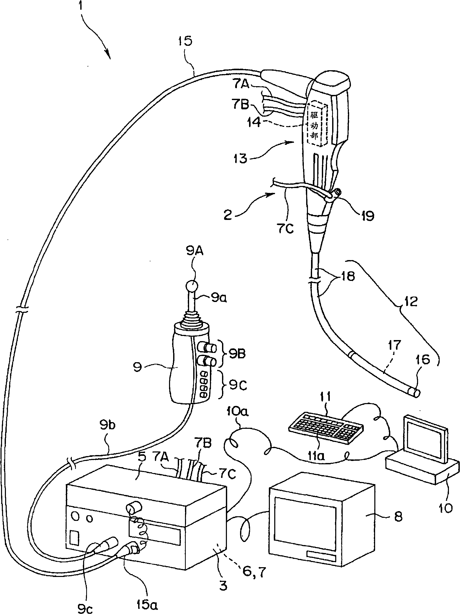
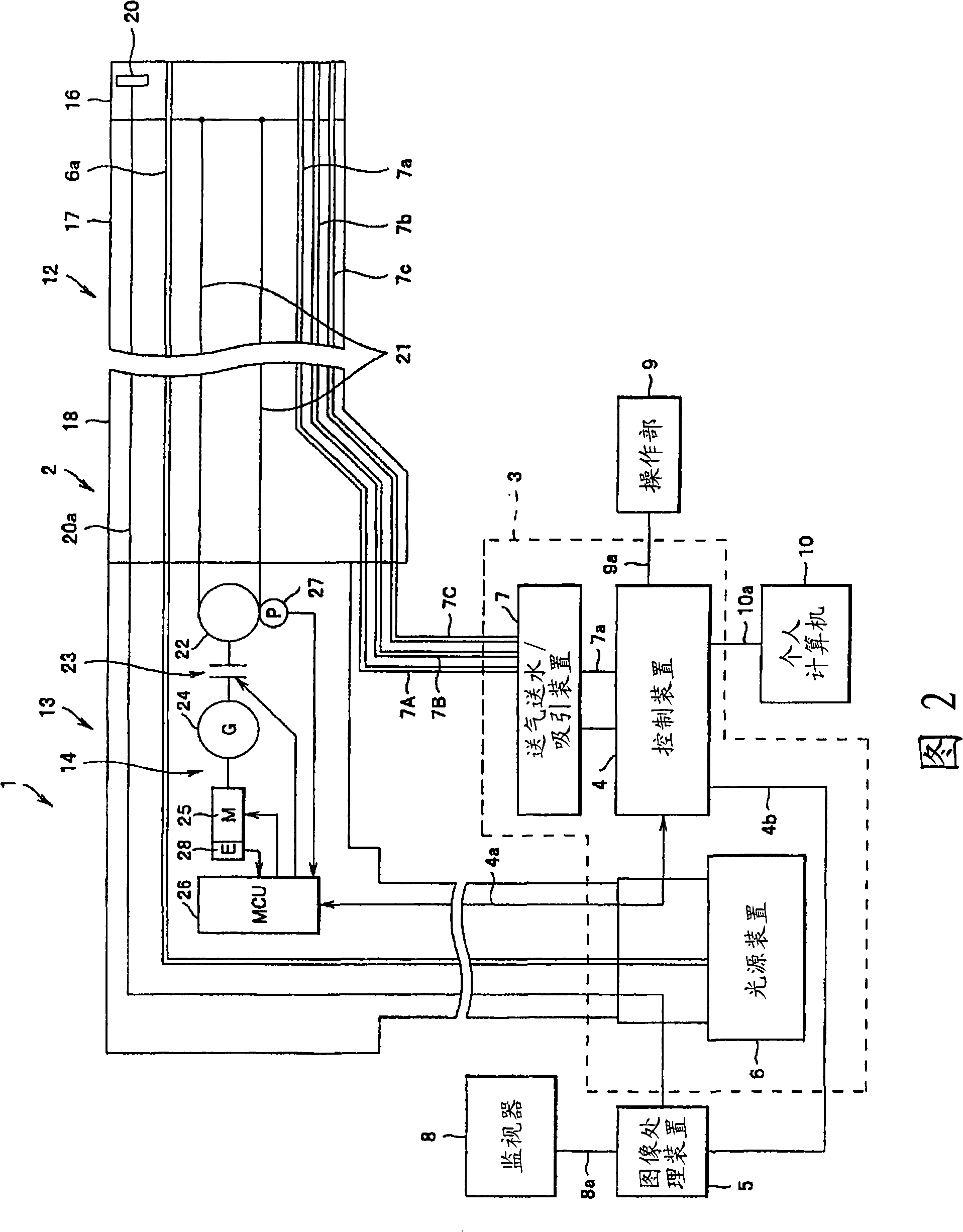
[0048] figure 1 Embodiment 1 of the electric bending endoscope device of the present invention will be described with FIG. 2 . figure 1 It is a system configuration diagram of the electric bending endoscope device. Figure 2 is shown figure 1 A diagram of the schematic structure of the motorized bending endoscope device.

[0049] Such as figure 1 As shown in FIG. 2, the electric bending endoscope device 1 of embodiment 1 has: an electric bending endoscope (hereinafter referred to simply as endoscope) 2; a control unit 3; The image signal transmitted by the signal cable 20a extending from the above-mentioned imaging element 20 of the scope 2 is generated as an image signal; the monitor 8 as a display device outputs the image signal generated by the above-mentioned image processing device 5, and displays the endoscopic image. ; the operation part 9, which is electrically connected with the above-mentioned control unit 3; Disassemble.

[0050] The above-mentioned endoscope 2...

Embodiment 2

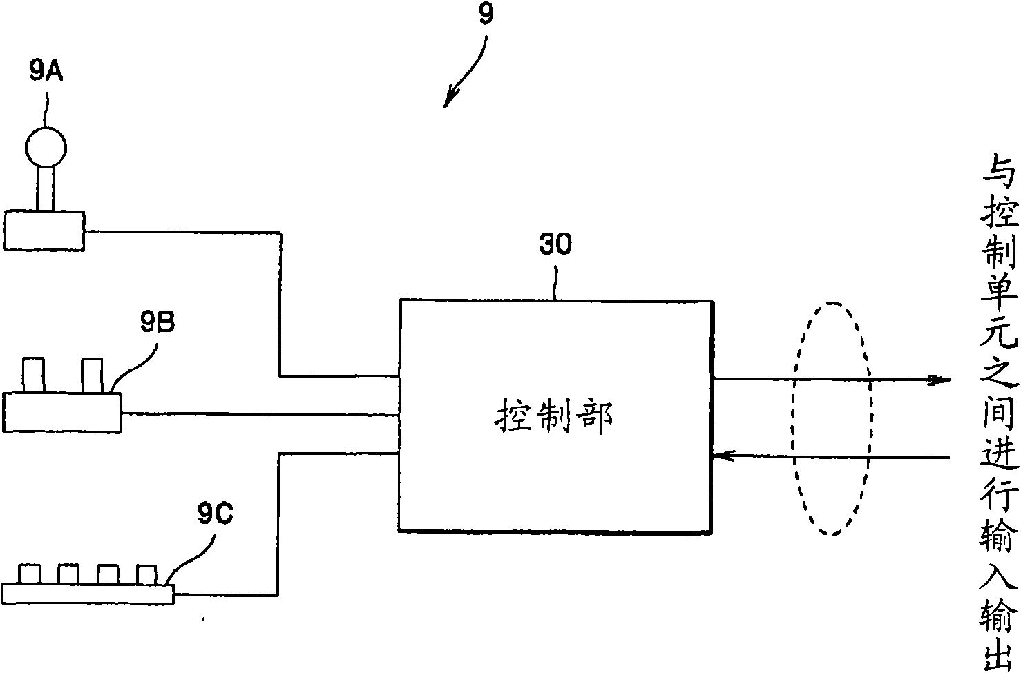
[0207] Figure 23 to Figure 27 It relates to Embodiment 2 of the electric bending endoscope device of the present invention. FIG. 23 is a block diagram showing the configuration of a control unit provided in the operation unit. FIG. 24 is a block diagram showing a specific configuration of the bending instruction unit signal processing unit in FIG. 23 . Figure 25 It is an explanatory diagram for setting an angle pattern described later of the operation unit by a determination process based on information of the identification ID in FIG. 23 . Figure 26 It is an electric signal coordinate diagram of the bending instruction part instruction signal after the signal processing in the game mode mentioned later. Figure 27 It is the electrical signal coordinate diagram of the indication signal of the bending indication part after the signal processing in the angle knob mode. In addition, in FIG. 23 and FIG. 24, the same reference numerals are assigned to the same constituent ele...

Embodiment 3

[0224] 28 and 29 relate to Embodiment 3 of the electric bending endoscope device of the present invention. FIG. 28 is a block diagram showing the configuration of a control unit provided in the operation unit. FIG. 29 is a block diagram showing a specific configuration of the bending instruction unit signal processing unit in FIG. 28 . In addition, FIG. 28 and FIG. 29 assign the same reference numerals to the same constituent elements as those of the above-mentioned embodiment 2 and omit description, and only the different parts will be described.

[0225] In this embodiment, as shown in FIG. 28 , a reference voltage signal (also referred to as a Ref reference voltage signal) as a reference from the bending instruction unit 9A is input to the bending instruction unit signal processing unit 31 .

[0226] That is, as shown in FIG. 29 , the above-mentioned Ref reference voltage signal is input to the A / D conversion circuit 41 of the bending instruction unit signal processing uni...


PUM


Abstract

An electrically bent endoscope device (1) has an endoscope (2) having a drive unit (13), a control unit (3), and an operation section (9) having a bend instruction section (9A). The operation section (9) has a joystick (9A) attached to the operation section (9) and functioning as the bend instruction section (9A). The operation section (9) also has a correction algorithm operation section (40) for creating an operation signal for the bend instruction section. The operation signal is created by converting an output range of an instruction signal of the joystick (9A) in such a way that the instruction signal coincides with a predetermined output range of an instruction signal of the bend instruction section, where the instruction signal is an operation signal that the operation section (9) outputs.

Description

technical field [0001] The present invention relates to an electric bending endoscope device having an electric bending endoscope. The electric bending endoscope has an operation part which can be mounted with a bending instruction part and outputs an operation signal of the bending instruction part. The bending is in a state corresponding to the operation signal of the bending instruction unit. Background technique [0002] Conventionally, endoscopes have been widely used. By inserting the elongated insertion portion of the endoscope into the body cavity, the surgeon can observe the internal organs of the body cavity and perform various treatments as necessary using the treatment instrument inserted in the treatment instrument channel. In addition, in the industrial field, workers can observe or inspect internal damage, corrosion, etc. of boilers, turbines, engines, chemical equipment, etc. by inserting the elongated insertion portion of the endoscope. [0003] In such an...

Claims


Application Information

Patent Timeline
IPC IPC(8): A61B1/00G02B23/24
CPCA61B1/0052A61B1/00039A61B1/0016A61B1/00133A61B1/00042
Inventor 伊藤诚悟小板桥正信
Owner OLYMPUS CORP
Learn More