
Apparatus for improving electrical arc ion plating deposition film quality

A technology of arc ion plating and thin film, which is applied in the direction of ion implantation plating, sputtering plating, vacuum evaporation plating, etc. It can solve the problems affecting the performance and life of coatings and films, and achieve the reduction of the content of large particles, regulation Effects with a large range and easy production

Inactive Publication Date: 2009-02-04
INST OF METAL RESEARCH - CHINESE ACAD OF SCI
View PDF0 Cites 7 Cited by
  • Summary
  • Abstract
  • Description
  • Claims
  • Application Information

AI Technical Summary

Problems solved by technology

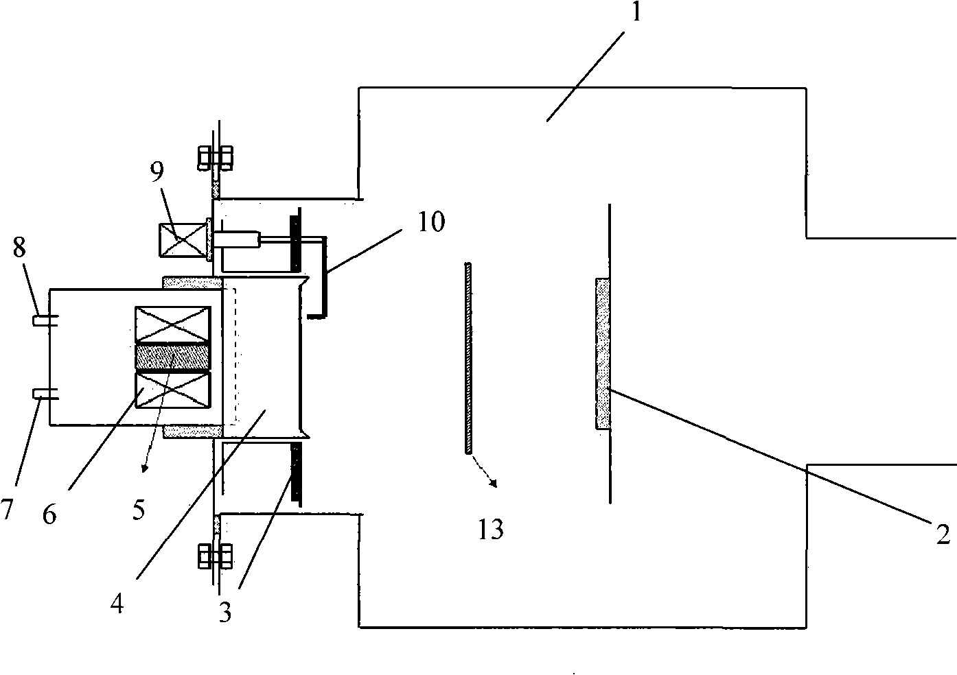
[0010] The purpose of the present invention is to provide a device for improving the quality of arc ion plating deposition film, to solve the problem that the performance and life of coating and film are seriously affected due to the existence of large particles in arc ion plating

Method used


Image

  • Apparatus for improving electrical arc ion plating deposition film quality
  • Apparatus for improving electrical arc ion plating deposition film quality
  • Apparatus for improving electrical arc ion plating deposition film quality

Examples


Embodiment 1

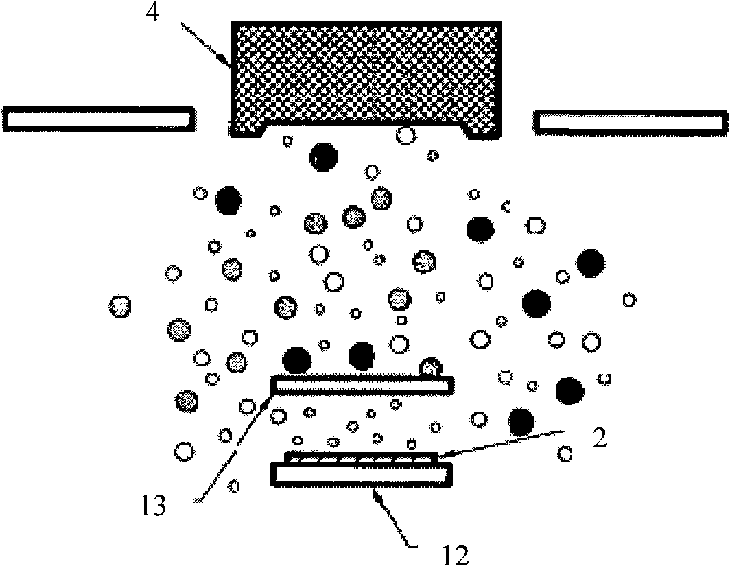
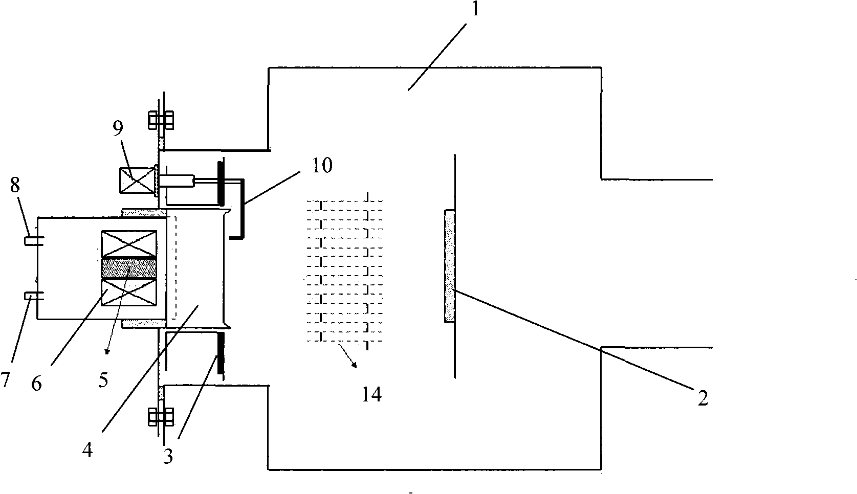
[0053] attached image 3 It is the embodiment device figure of scheme one of the present invention, and figure 2 The difference is that the double-layer perforated baffles 14 (perforated baffles I15, perforated baffles II16) are placed between the cathode target 4 and the substrate 2, and the distance between the target 4 and the substrate 2 is equal. The structure of double-layer perforated baffle plate 14 is as Figure 4 As shown, the perforated baffle I15 and the perforated baffle II16 in the double-layer perforated baffle 14 are coaxially placed in parallel, and are also placed coaxially with the target 4 and the substrate 2. The perforated baffle I15 and the perforated baffle The distance between II16 is 50mm. In this embodiment, the baffle plate I15 with holes and the baffle plate II16 with holes are made of stainless steel sheet, the shape of the baffle plates is a regular hexagon, and the length between opposite sides is 100mm. The shape of the hole is circular, th...

Embodiment 2

[0056] attached Figure 8 It is an embodiment device diagram of the second scheme of the present invention. On the basis of Embodiment 1, an enhanced magnetic field coil 11 is added to the substrate, and the enhanced magnetic field coil 11 is placed coaxially with the target material 4 and the double-layer perforated baffle plate 14. The distance between the enhanced magnetic field coil 11 and the substrate 2 can be adjusted. The enhanced magnetic field coil 11 is circular in shape, with an inner diameter of 100mm, an outer diameter of 180mm, and a thickness of 50mm. The electromagnetic coil is wound with QZY-2 high-temperature enameled wire, and the coil is wrapped with high-temperature-resistant glass cloth to ensure high-temperature insulation. The coil leads use high temperature wires and are covered with porcelain tubes for protection. The coil current is regulated by a DC voltage regulator, and adjusting the magnitude of the current can change the strength of the magnet...


PUM


Abstract

The invention relates to the field of film preparation, in particular to a device for improving the quality of arc ion plated deposition film which is used to solve the problems that because large particles existing in arc ion plating severely impact the performance and the service life of the coating and the film, etc. In the invention, a double-layer baffle with hole is arranged between the target and the substrate of the arc ion plated deposition device, coaxial with the target and the substrate, and a generating device used to strengthen the magnetic field is arranged behind the substrate. The invention is a convenient device used in the arc ion plating deposition process, which is used to reduce the content of large particles in the film, reduce the roughness of the surface of the film and improve the performance and service life of the film, and thus meeting the requirements for preparing high-quality film.

Description

technical field [0001] The invention relates to the field of film preparation, in particular to a device for improving the quality of an arc ion plating deposited film, which is used to reduce the content of large particles in the film, reduce the surface roughness of the film, and improve the performance and life of the film. Background technique [0002] Arc ion coating technology is an advanced ion coating technology today. Due to its simple structure, high ionization rate (70%-80%), high incident particle energy, good diffraction, and a series of advantages such as low temperature deposition, The arc ion plating technology has been rapidly developed and widely used, showing great economic benefits and industrial application prospects. [0003] Arc ion plating is a coating technology based on the principle of gas discharge plasma physical vapor deposition. This technology relies on the local high temperature of the arc spot generated on the surface of the cathode target ...

Claims


Application Information

Patent Timeline
Patent Type & Authority Applications(China)
IPC IPC(8): C23C14/32
Inventor 肖金泉郎文昌孙超宫骏赵彦辉杜昊闻立时
Owner INST OF METAL RESEARCH - CHINESE ACAD OF SCI
Learn More