Rotation position control method and apparatus for switching reluctance motor

A technology of switched reluctance motor and rotation position, which is applied in the direction of single motor speed/torque control, control using feedback, electronic commutator, etc. It can solve the problem of stepping motor out of step and stepping motor with weak load capacity , Motor out of step and other problems, to achieve the effect of improving the position control accuracy

Active Publication Date: 2009-02-04
BYD CO LTD
View PDF0 Cites 18 Cited by
  • Summary
  • Abstract
  • Description
  • Claims
  • Application Information

AI Technical Summary

Problems solved by technology

However, because the load capacity of the stepper motor is not strong, the motor is prone to out-of-step phenomenon when the load changes. When the car is parked due to different road conditions, the load when locking and unlocking the gearbox will be different, and the car's The power supply will fluctuate depending on the electrical load of the vehicle
Therefore, the stepper motor is prone to out-of-step phenomenon when parking

Method used


Image

  • Rotation position control method and apparatus for switching reluctance motor
  • Rotation position control method and apparatus for switching reluctance motor
  • Rotation position control method and apparatus for switching reluctance motor

Examples


Embodiment Construction

[0035] The traditional switched reluctance motor control uses frequency conversion speed regulation to comprehensively control the motor speed and output power, and its stable working area is in the medium and high speed area (greater than 1000 rpm). In the low-speed area, the traditional switched reluctance motor control method adopts "voltage PWM control", that is, the difference between the speed setting value and the actual speed is used to modulate the DC voltage and add it to the effective time of the conduction phase winding to change the effective time of the external voltage. value, thereby changing the torque.

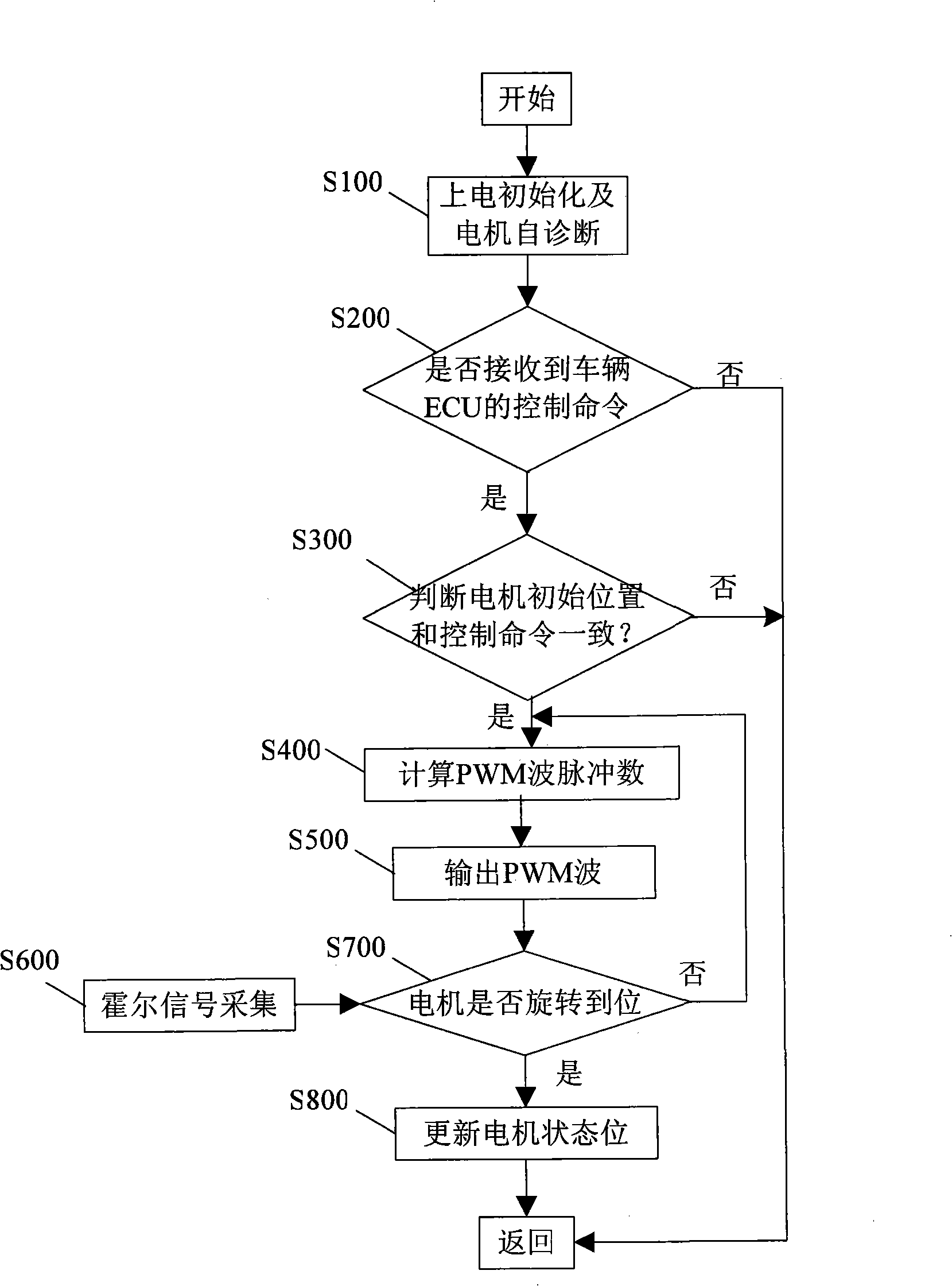
[0036] The control method of the switched reluctance motor in the present invention adopts the method of counting walking pulses, and the features and advantages of the present invention will be described in detail through the embodiments in conjunction with the accompanying drawings.

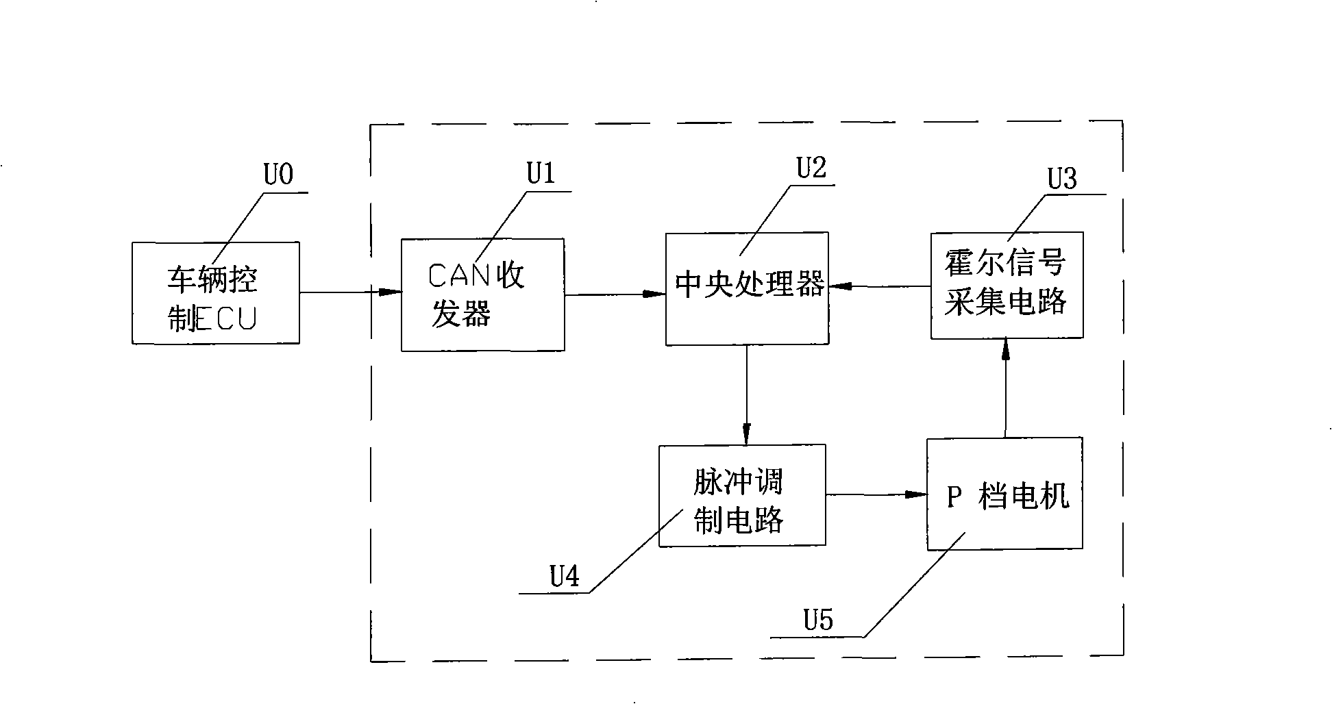
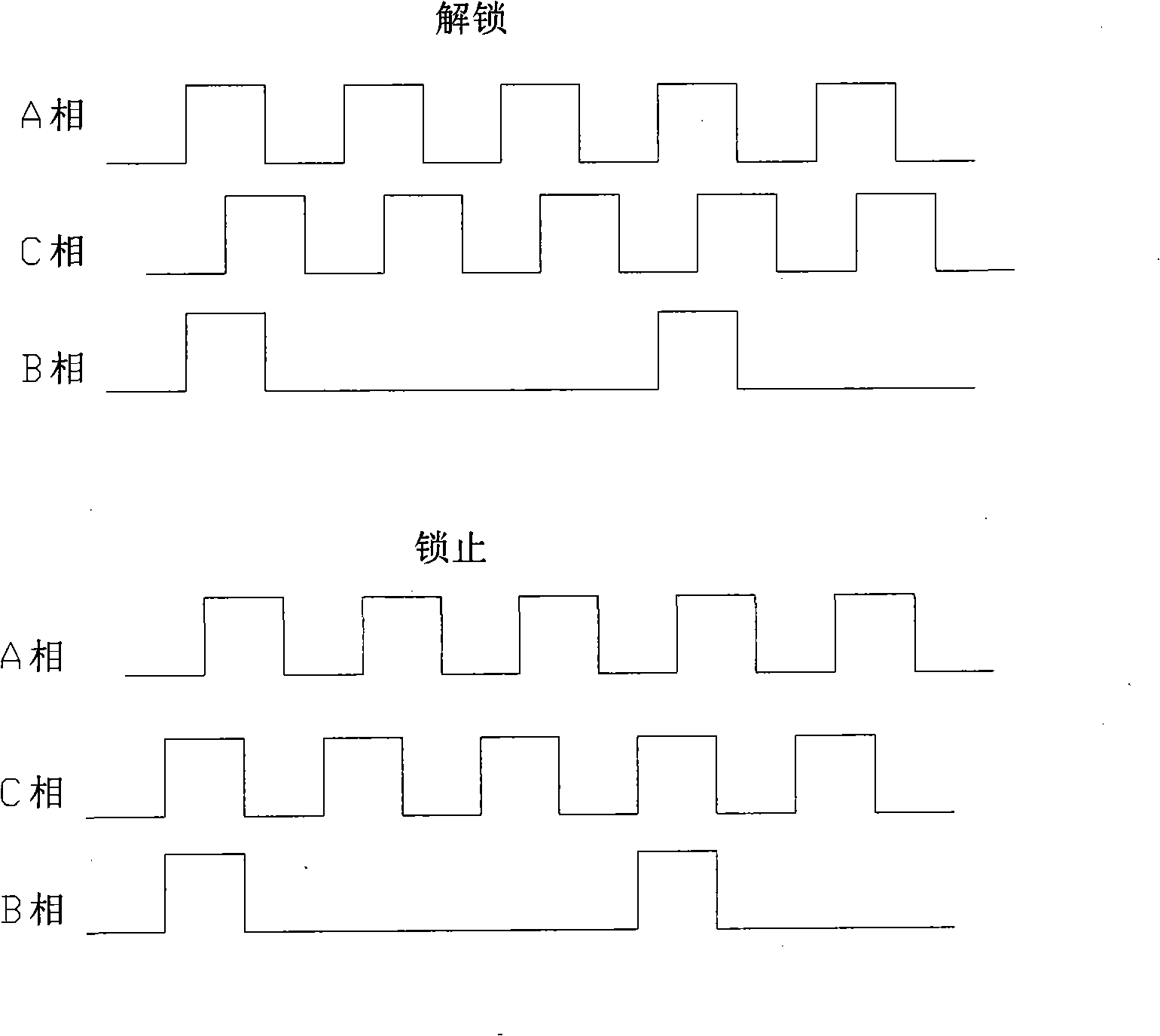
[0037] The locked position of the P gear motor controller refers to the p...


PUM


Abstract

The invention discloses a rotational position control method of a switched reluctance motor as well as a control device, and the method comprises the following steps: A1. receiving a control command for rotating the switched reluctance motor to a specific position; B1. comparing the specific position in the control command with an initial position of the switched reluctance motor, if consistent, executing the step C1, or else, executing the step D1; C1. not executing the control command of the switched reluctance motor; and D1. calculating the pulse number of PWM waves required to be output according to the initial position of the switched reluctance motor and driving the switched reluctance motor to rotate according to the calculated pulse number of output PWM waves. The method and the device adopt the switched reluctance motor as a P gear of an automobile to lock up the motor, and adopt the control means of counting the walking pulses by the output specific PWM pulse number, and can compensate the desynchronizing of the motor when in control, thereby improving the position control precision of the switched reluctance motor.

Description

【Technical field】 [0001] The invention relates to a control method of a motor, in particular to a method and a control device for controlling the rotational position of a switched reluctance motor. 【Background technique】 [0002] On an electric car, when the car is in the parking gear (P gear), the control system will drive the motor to lock the mechanical structure of the gearbox, so as to achieve the purpose of parking. Since the number of electric pulses of the stepping motor is proportional to the mechanical angular displacement of the motor, the control method is to use the number of walking pulses to control the number of running steps of the motor, so the stepping motor is usually used as the locking motor of the P gear. Ability to control to ensure the motor spins to the correct position. However, because the load capacity of the stepper motor is not strong, the motor is prone to out-of-step phenomenon when the load changes. When the car is parked due to different r...

Claims


Application Information

Patent Timeline
Patent Type & Authority Applications(China)
IPC IPC(8): H02P6/08H02P6/16G05D3/12
Inventor 郭良祖波周旭光
Owner BYD CO LTD
Why Eureka
Try Eureka